Take your sound to the next level with SSM2167-1RMZ-R7 and PIC32MZ2048EFM100
Speak up, make an impact

Published Oct 02, 2023
Click board™
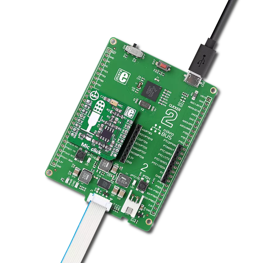
MIC 3 Click
Dev. board
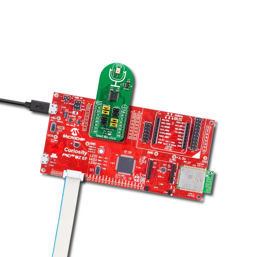
Curiosity PIC32 MZ EF
Compiler
NECTO Studio
MCU
PIC32MZ2048EFM100
Unleash your creativity and achieve unparalleled sound clarity with our guide to building microphone system
A
A
Hardware Overview
How does it work?
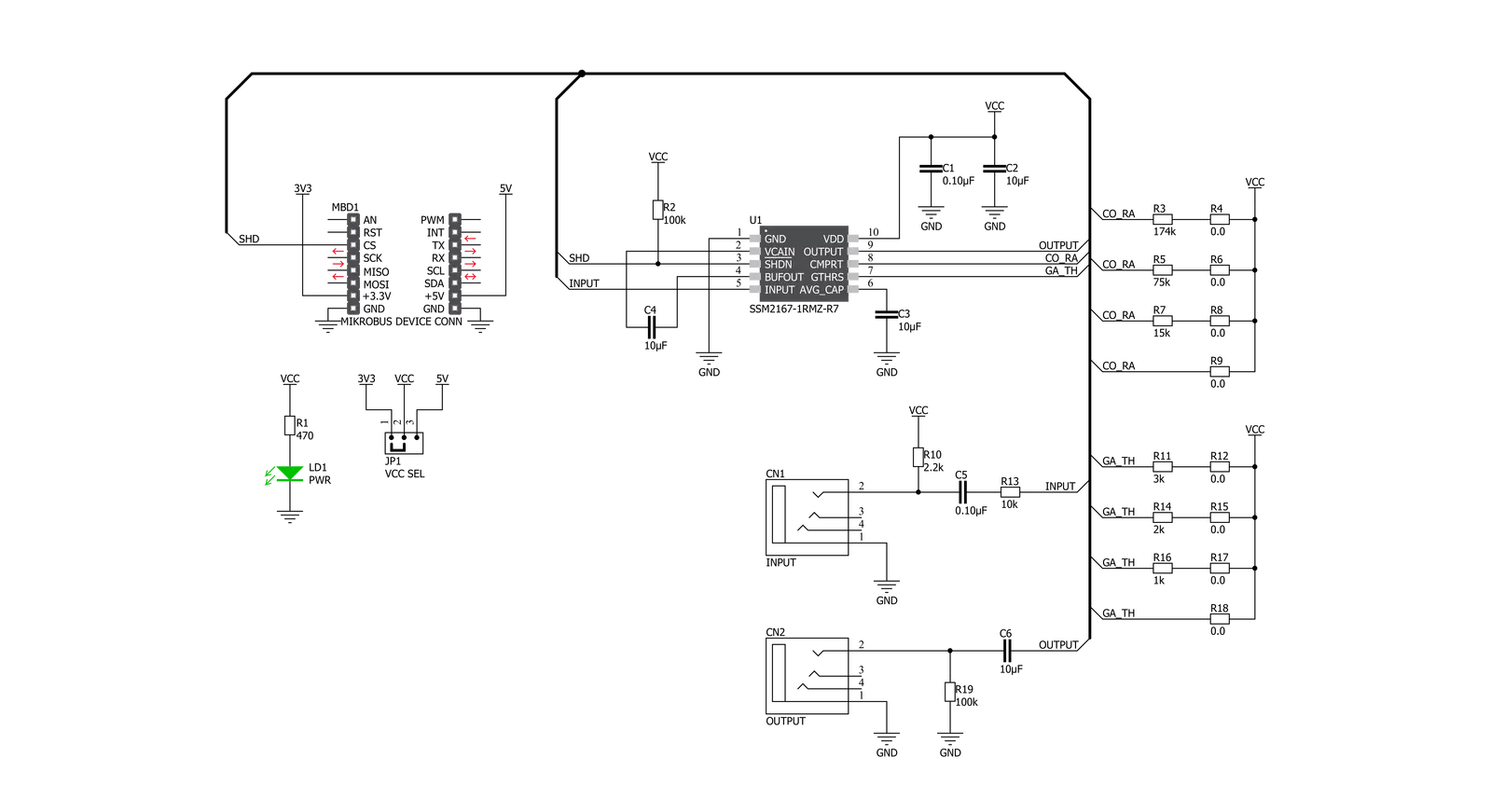
MIC 3 Click is based on the SSM2167-1RMZ-R7 from Analog Devices, a complete and flexible solution for conditioning microphone inputs in personal electronics and computer audio systems. The Click board™ is also excellent for improving vocal clarity in communications and public address systems. A low noise voltage-controlled amplifier (VCA) provides a gain that is dynamically adjusted by a control loop to maintain a set compression characteristic. The MIC 3 Click provides two operation settings, these settings are selectable with NOISE G. COMPR. jumpers. The MIC 3 Click
provides four different preset values of the noise gate threshold. Experiment with these values by varying the gate. The noise gate threshold is a programmable point using an external resistor. The downward expansion threshold may be set between −40 dBV and −55 dBV. The Click board™ provides four different preset values of the compression ratio. Changing the scaling of the control signal fed to the VCA causes a change in the circuit compression ratio.Lowering RCOMP gives smaller compression ratios. Automatic Gain Control (AGC) performance is achieved with
compression ratios between 2:1 and 10:1, and is dependent on the application. Shorting RCOMP disables the AGC function, setting the compression equal to 1:1. This Click board™ can operate with either 3.3V or 5V logic voltage levels selected via the VCC SEL jumper. This way, both 3.3V and 5V capable MCUs can use the communication lines properly. Also, this Click board™ comes equipped with a library containing easy-to-use functions and an example code that can be used as a reference for further development.

Features overview
Development board
Curiosity PIC32 MZ EF development board is a fully integrated 32-bit development platform featuring the high-performance PIC32MZ EF Series (PIC32MZ2048EFM) that has a 2MB Flash, 512KB RAM, integrated FPU, Crypto accelerator, and excellent connectivity options. It includes an integrated programmer and debugger, requiring no additional hardware. Users can expand
functionality through MIKROE mikroBUS™ Click™ adapter boards, add Ethernet connectivity with the Microchip PHY daughter board, add WiFi connectivity capability using the Microchip expansions boards, and add audio input and output capability with Microchip audio daughter boards. These boards are fully integrated into PIC32’s powerful software framework, MPLAB Harmony,
which provides a flexible and modular interface to application development a rich set of inter-operable software stacks (TCP-IP, USB), and easy-to-use features. The Curiosity PIC32 MZ EF development board offers expansion capabilities making it an excellent choice for a rapid prototyping board in Connectivity, IOT, and general-purpose applications.

Microcontroller Overview
MCU Card / MCU

Architecture
PIC32
MCU Memory (KB)
2048
Silicon Vendor
Microchip
Pin count
100
RAM (Bytes)
524288
Used MCU Pins
mikroBUS™ mapper
Take a closer look
Click board™ Schematic
Step by step
Project assembly

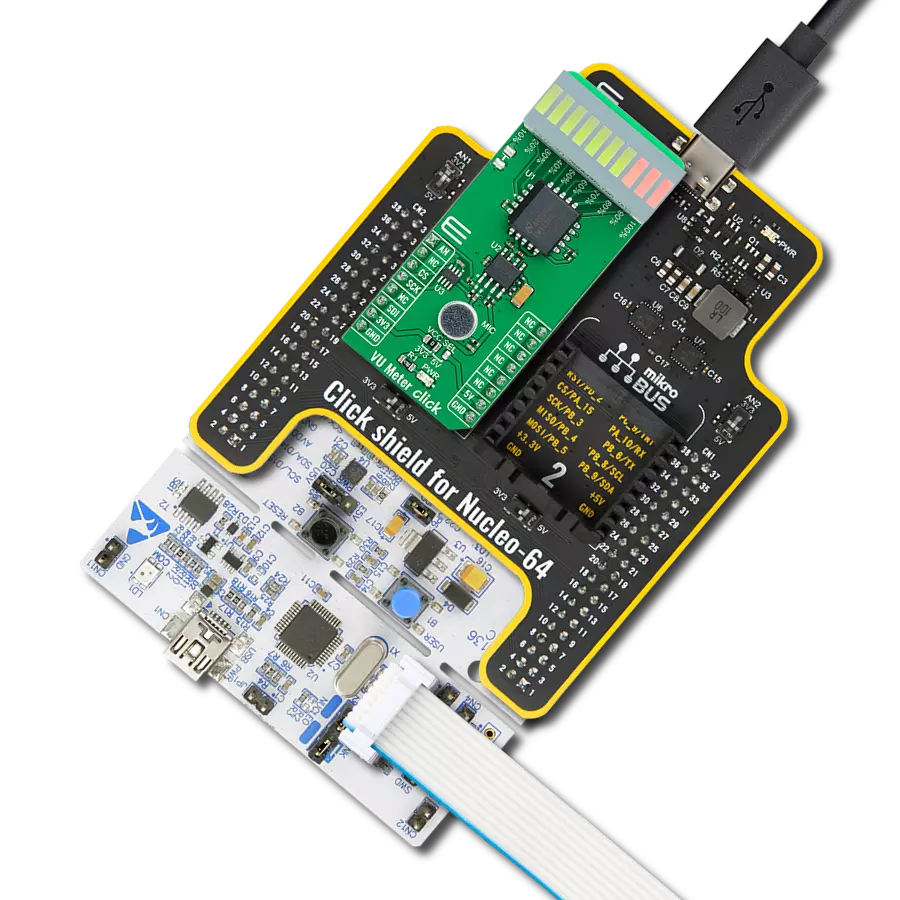
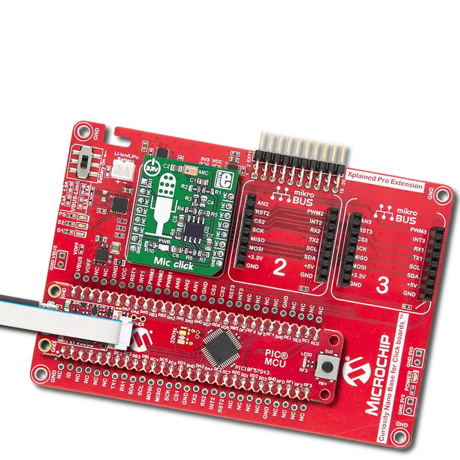
Start by selecting your development board and Click board™. Begin with the Curiosity PIC32 MZ EF as your development board.


Software Support
Library Description
This library contains API for MIC 3 Click driver.
Key functions:
mic3_shd_pin_set- MIC 3 SHD pin setting function.
Open Source
Code example
The complete application code and a ready-to-use project are available through the NECTO Studio Package Manager for direct installation in the NECTO Studio. The application code can also be found on the MIKROE GitHub account.
/*!
 * @file main.c
 * @brief MIC 3 Click Example.
 *
 * # Description
 * This is an example that demonstrates the use of the MIC 3 Click board.
 *
 * The demo application is composed of two sections :
 *
 * ## Application Init
 * Initialization of SHD to output and log module, maping GPIO for Mikrobus1, and seting SHD pin to
 * HIGH state.
 *
 * ## Application Task
 * Turning microphone on for the 5 seconds, then turning it off for 5 seconds.
 *
 * @author Stefan Ilic
 *
 */

#include "board.h"
#include "log.h"
#include "mic3.h"

static mic3_t mic3;   /**< MIC 3 Click driver object. */
static log_t logger;    /**< Logger object. */

void application_init ( void )
{
    log_cfg_t log_cfg;  /**< Logger config object. */
    mic3_cfg_t mic3_cfg;  /**< Click config object. */

    /**
     * Logger initialization.
     * Default baud rate: 115200
     * Default log level: LOG_LEVEL_DEBUG
     * @note If USB_UART_RX and USB_UART_TX
     * are defined as HAL_PIN_NC, you will
     * need to define them manually for log to work.
     * See @b LOG_MAP_USB_UART macro definition for detailed explanation.
     */
    LOG_MAP_USB_UART( log_cfg );
    log_init( &logger, &log_cfg );
    log_info( &logger, " Application Init " );

    // Click initialization.
    mic3_cfg_setup( &mic3_cfg );
    MIC3_MAP_MIKROBUS( mic3_cfg, MIKROBUS_1 );
    if ( DIGITAL_OUT_UNSUPPORTED_PIN == mic3_init( &mic3, &mic3_cfg ) ) {
        log_error( &logger, " Application Init Error. " );
        log_info( &logger, " Please, run program again... " );

        for ( ; ; );
    }
    mic3_default_cfg ( &mic3 );
    log_info( &logger, " Application Task " );
}

void application_task ( void )
{
    log_printf( &logger, " - Microphone is turned on  - \r\n" );
    mic3_shd_pin_set( &mic3, MIC3_PIN_STATE_HIGH );
    Delay_ms ( 1000 );
    Delay_ms ( 1000 );
    Delay_ms ( 1000 );
    Delay_ms ( 1000 );
    Delay_ms ( 1000 );

    log_printf( &logger, " - Microphone is turned off  - \r\n" );
    mic3_shd_pin_set( &mic3, MIC3_PIN_STATE_LOW );
    Delay_ms ( 1000 );
    Delay_ms ( 1000 );
    Delay_ms ( 1000 );
    Delay_ms ( 1000 );
    Delay_ms ( 1000 );
}

int main ( void )
{
    /* Do not remove this line or clock might not be set correctly. */
    #ifdef PREINIT_SUPPORTED
    preinit();
    #endif

    application_init( );

    for ( ; ; )
    {
        application_task( );
    }

    return 0;
}

// ------------------------------------------------------------------------ END
Additional Support
Resources
Category:Microphone