Experience the next level of connectivity with THVD1426 and PIC32MZ2048EFM100
Data harmony in every byte: Unleash the potential of full-duplex RS485

Published Nov 12, 2023
Click board™
RS485 8 Click
Dev. board
Curiosity PIC32 MZ EF
Compiler
NECTO Studio
MCU
PIC32MZ2048EFM100
Empower your network with our full-duplex RS485 transceiver, offering a robust solution for real-time, high-speed, and bidirectional data exchange, setting a new standard for communication reliability.
A
A
Hardware Overview
How does it work?
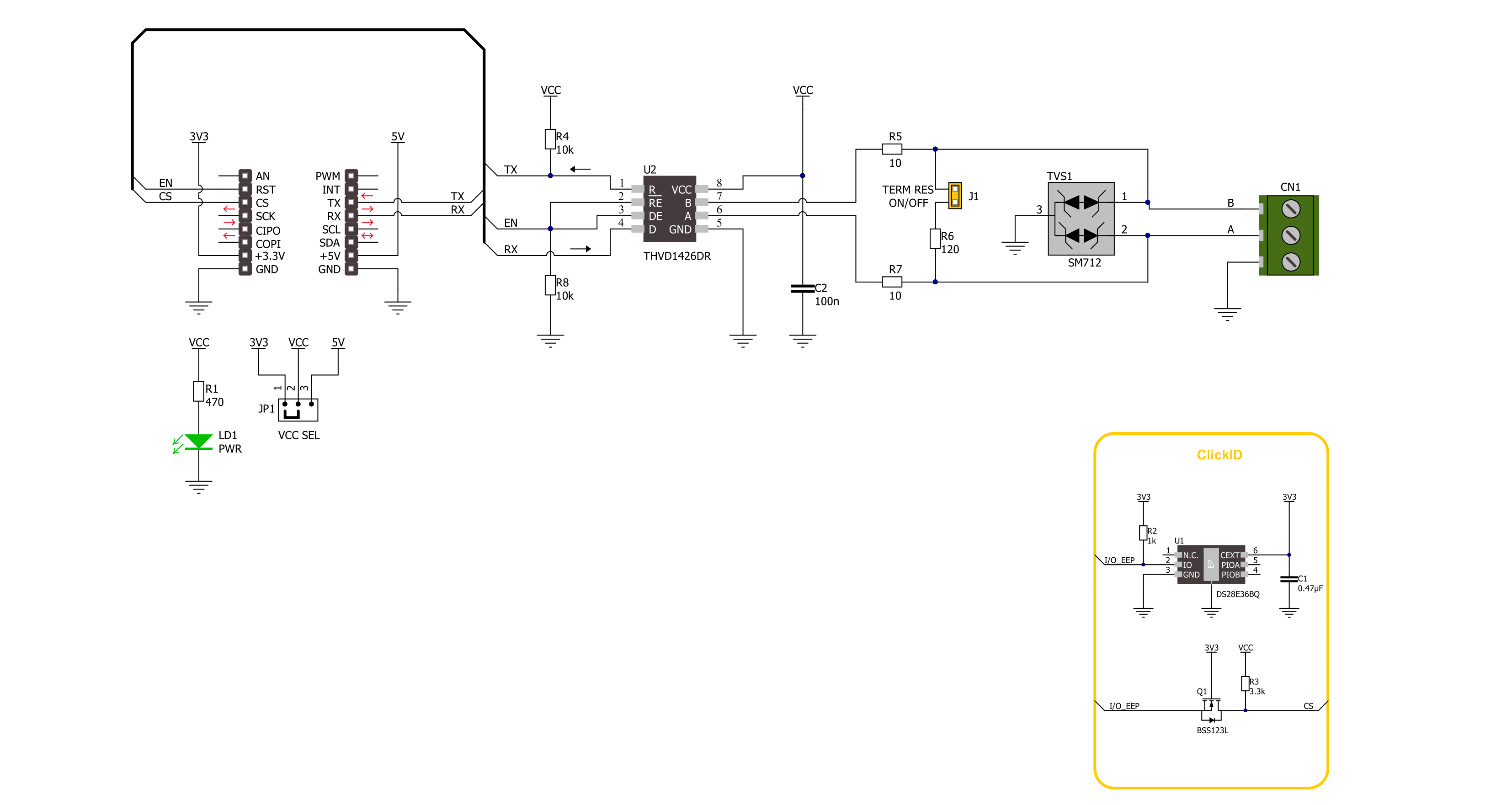
RS485 8 Click is based on the THVD1426, an RS485 transceiver with auto-direction control and ESD protection from Texas Instruments. The THVD1426 has one termination resistor over the A/B that can be enabled over the TERM jumper. The RS485 8 Click comes with the SM712, a 600W asymmetrical TVS diode array from Littelfuse, along with the termination resistor. This diode array is designed to protect the RS485 applications with asymmetrical working voltages from -7V up to 12V, thus making it safe from damage due to
electrostatic discharge, fast electrical transients, and lightning-induced surges. Both the diode array and the termination resistor are placed near the RS485 screw terminal, with which you can connect the RS485 8 Click to your application's other end. RS485 8 Click uses the UART interface to communicate with the host MCU with commonly used UART RX and TX pins. The auto-direction mode on the RS485 8 Click is set by default and disabled with a pull-down resistor. It can be enabled with the logic HIGH state on the
EN pin of the mikroBUS™ socket. You can control the driver and receiver using the data input pin RX by enabling the transceiver. This Click board™ can operate with either 3.3V or 5V logic voltage levels selected via the VCC SEL jumper. This way, both 3.3V and 5V capable MCUs can use the communication lines properly. Also, this Click board™ comes equipped with a library containing easy-to-use functions and an example code that can be used as a reference for further development.

Features overview
Development board
Curiosity PIC32 MZ EF development board is a fully integrated 32-bit development platform featuring the high-performance PIC32MZ EF Series (PIC32MZ2048EFM) that has a 2MB Flash, 512KB RAM, integrated FPU, Crypto accelerator, and excellent connectivity options. It includes an integrated programmer and debugger, requiring no additional hardware. Users can expand
functionality through MIKROE mikroBUS™ Click™ adapter boards, add Ethernet connectivity with the Microchip PHY daughter board, add WiFi connectivity capability using the Microchip expansions boards, and add audio input and output capability with Microchip audio daughter boards. These boards are fully integrated into PIC32’s powerful software framework, MPLAB Harmony,
which provides a flexible and modular interface to application development a rich set of inter-operable software stacks (TCP-IP, USB), and easy-to-use features. The Curiosity PIC32 MZ EF development board offers expansion capabilities making it an excellent choice for a rapid prototyping board in Connectivity, IOT, and general-purpose applications.

Microcontroller Overview
MCU Card / MCU

Architecture
PIC32
MCU Memory (KB)
2048
Silicon Vendor
Microchip
Pin count
100
RAM (Bytes)
524288
Used MCU Pins
mikroBUS™ mapper
Take a closer look
Click board™ Schematic
Step by step
Project assembly

Start by selecting your development board and Click board™. Begin with the Curiosity PIC32 MZ EF as your development board.


Software Support
Library Description
This library contains API for RS485 8 Click driver.
Key functions:
rs4858_generic_write- RS485 8 data writing function.rs4858_generic_read- RS485 8 data reading function.rs4858_enable_device- RS485 8 enable the device function.
Open Source
Code example
The complete application code and a ready-to-use project are available through the NECTO Studio Package Manager for direct installation in the NECTO Studio. The application code can also be found on the MIKROE GitHub account.
/*!
 * @file main.c
 * @brief RS485 8 Click Example.
 *
 * # Description
 * This example reads and processes data from RS485 8 Clicks.
 * The library also includes a function for enabling/disabling
 * the receiver or driver and data writing or reading.
 *
 * The demo application is composed of two sections :
 *
 * ## Application Init
 * Initializes the driver and performs the Click default configuration.
 *
 * ## Application Task
 * This example demonstrates the use of the RS485 8 Click board.
 * The app sends a "MikroE" message, reads the received data and parses it.
 * Results are being sent to the UART Terminal, where you can track their changes.
 *
 * ## Additional Function
 * - static err_t rs4858_process ( void )
 *
 * @author Stefan Ilic
 *
 */

#include "board.h"
#include "log.h"
#include "rs4858.h"

#define PROCESS_BUFFER_SIZE 200

// Comment out the line below in order to switch the application mode to receiver.
#define DEMO_APP_TRANSMITTER

static rs4858_t rs4858;
static log_t logger;

uint8_t data_buf[ 8 ] = { 'M', 'i', 'k', 'r', 'o', 'E', '\r', '\n' };

static uint8_t app_buf[ PROCESS_BUFFER_SIZE ] = { 0 };
static int32_t app_buf_len = 0;

/**
 * @brief RS485 8 data reading function.
 * @details This function reads data from device and concatenates data to application buffer.
 * @param[in] ctx : Click context object.
 * See #rs4858_t object definition for detailed explanation.
 * @return @li @c  0 - Read some data.
 *         @li @c -1 - Nothing is read.
 * See #err_t definition for detailed explanation.
 * @note None.
 */
static err_t rs4858_process ( void );

void application_init ( void )
{
    log_cfg_t log_cfg;  /**< Logger config object. */
    rs4858_cfg_t rs4858_cfg;  /**< Click config object. */

    /**
     * Logger initialization.
     * Default baud rate: 115200
     * Default log level: LOG_LEVEL_DEBUG
     * @note If USB_UART_RX and USB_UART_TX
     * are defined as HAL_PIN_NC, you will
     * need to define them manually for log to work.
     * See @b LOG_MAP_USB_UART macro definition for detailed explanation.
     */
    LOG_MAP_USB_UART( log_cfg );
    log_init( &logger, &log_cfg );
    log_info( &logger, " Application Init " );

    // Click initialization.
    rs4858_cfg_setup( &rs4858_cfg );
    RS4858_MAP_MIKROBUS( rs4858_cfg, MIKROBUS_2 );
    if ( UART_ERROR == rs4858_init( &rs4858, &rs4858_cfg ) )
    {
        log_error( &logger, " Communication init." );
        for ( ; ; );
    }

    rs4858_default_cfg ( &rs4858 );

#ifdef DEMO_APP_TRANSMITTER
    log_info( &logger, "---- Transmitter mode ----" );
#else
    log_info( &logger, "---- Receiver mode ----" );
#endif

    log_info( &logger, " Application Task " );
    Delay_ms ( 100 );
}

void application_task ( void )
{
#ifdef DEMO_APP_TRANSMITTER
    rs4858_generic_write( &rs4858, data_buf, strlen( data_buf ) );
    log_info( &logger, "---- Data sent ----" );
    Delay_ms ( 1000 );
    Delay_ms ( 1000 );
#else
    rs4858_process( );
#endif
}

int main ( void )
{
    /* Do not remove this line or clock might not be set correctly. */
    #ifdef PREINIT_SUPPORTED
    preinit();
    #endif

    application_init( );

    for ( ; ; )
    {
        application_task( );
    }

    return 0;
}

static err_t rs4858_process ( void )
{
    int32_t rx_size;
    char rx_buf[ PROCESS_BUFFER_SIZE ] = { 0 };
    rx_size = rs4858_generic_read( &rs4858, rx_buf, PROCESS_BUFFER_SIZE );
    if ( rx_size > 0 )
    {
        log_printf( &logger, "%s", rx_buf );
        return RS4858_OK;
    }
    return RS4858_ERROR;
}

// ------------------------------------------------------------------------ END


