Achieve reliable wireless communication in industrial automation and IoT with the WIRL-PRO2 Thyone-I (2611011021000) and PIC32MZ2048EFM100
Data transmission in the 2.4GHz license-free band supporting both point-to-point or mesh networking topologies

Published Jul 01, 2024
Click board™
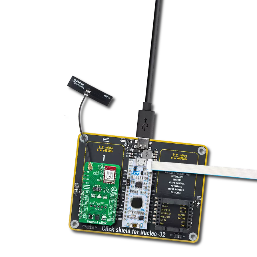
Thyone-I Click
Dev. board
Curiosity PIC32 MZ EF
Compiler
NECTO Studio
MCU
PIC32MZ2048EFM100
Create wireless connectivity for various industrial or IoT devices to transmit data to gateways or cloud platforms for monitoring and control
A
A
Hardware Overview
How does it work?
Thyone-I Click is based on the WIRL-PRO2 Thyone-I (2611011021000) module from Würth Elektronik. This radio sub-module provides wireless communication for various devices, including control systems, remote controls, and sensor nodes. Operating within the globally available 2.4GHz license-free band, the Thyone-I ensures secure and reliable data transmission in both point-to-point and mesh configurations. Pre-loaded with Würth Elektronik's WE-ProWare radio stack, it offers high flexibility and reliability. The module interfaces with the host system via a serial UART interface, simplifying the configuration and control of the radio through an easy command interface. Additionally, it features a transparent mode for cable replacement applications, functioning as a serial-to-radio adapter. The Thyone-I module carries versatile features, from low-power, long-range capabilities to line-powered, high-throughput performance, making it energy-efficient. Users can choose between the onboard PCB antenna for compact designs or an external antenna for long-range applications, thanks to the onboard ANT u.Fl connector. The module supports a radio profile with a 2Mbit/s data transmission rate, leading to an
effective end-to-end throughput of approximately 400kbit/s. It also offers embedded security with a secure bootloader and hardware-accelerated end-to-end encryption. Other features include repeater functionality for simple flooding mesh network creation. Pre-flashed, tested, and ready to use out-of-the-box, the Thyone-I module complies with various regulatory requirements, making it suitable for global use. Operating in the 2.4GHz band, it can be configured to use one of the 39 channels from 2403MHz to 2479MHz. The module's transmit power ranges from -40dBm to +8dBm, affecting both radio range and current consumption. When powered on, the Thyone-I can be put in Command or Transparent modes of operations via the MODE switch (clearly marked on the board T for Transparent and C for Command). Command mode is the standard mode of operation for Thyone-I. The module can be configured and controlled in this mode using the command interface. In the transparent mode, the module acts as a transparent UART-radio bridge, and any data received on the UART interface will be sent via radio. As mentioned, communication between the Thyone-I module and the host MCU is established
through a UART interface, standard UART RX and TX pins, and hardware flow control pins (CTS/RTS). The default communication speed is 115200bps, ensuring efficient data exchange. The board also includes a reset (RST) pin for hard resetting the module, a wake-up pin for waking the module from Sleep mode, and a Boot (BT) pin to trigger the bootloader mode for firmware updates when set to a low logic level during reset. It also features three LED indicators: a yellow BUSY LED indicating data transmission activity in Transparent mode and blue and green LEDs (LD1 for TX and LD2 for RX) for RF transmission status. Additionally, it has GPIO and Debug pins. The GPIO pins (B1 to B6) can be configured and controlled for various digital I/O functions, while the Debug pins utilize the Serial Wire Debug (SWD) interface for debugging purposes. This Click board™ can be operated only with a 3.3V logic voltage level. The board must perform appropriate logic voltage level conversion before using MCUs with different logic levels. Also, it comes equipped with a library containing functions and an example code that can be used as a reference for further development.

Features overview
Development board
Curiosity PIC32 MZ EF development board is a fully integrated 32-bit development platform featuring the high-performance PIC32MZ EF Series (PIC32MZ2048EFM) that has a 2MB Flash, 512KB RAM, integrated FPU, Crypto accelerator, and excellent connectivity options. It includes an integrated programmer and debugger, requiring no additional hardware. Users can expand
functionality through MIKROE mikroBUS™ Click™ adapter boards, add Ethernet connectivity with the Microchip PHY daughter board, add WiFi connectivity capability using the Microchip expansions boards, and add audio input and output capability with Microchip audio daughter boards. These boards are fully integrated into PIC32’s powerful software framework, MPLAB Harmony,
which provides a flexible and modular interface to application development a rich set of inter-operable software stacks (TCP-IP, USB), and easy-to-use features. The Curiosity PIC32 MZ EF development board offers expansion capabilities making it an excellent choice for a rapid prototyping board in Connectivity, IOT, and general-purpose applications.

Microcontroller Overview
MCU Card / MCU

Architecture
PIC32
MCU Memory (KB)
2048
Silicon Vendor
Microchip
Pin count
100
RAM (Bytes)
524288
You complete me!
Accessories
WiFi 2.4GHz/5.4GHz Active FPC Antenna (W3918B0100) is an active flat patch antenna from Pulse Electronics ideal for WiFi 6E, Bluetooth, ZigBee, ISM band radios, IoT, M2M, and more. With dual-frequency capabilities in a range of 2.4-2.5GHz and 4.9-5.925GHz, with central frequencies of 2.4GHz and 5.4GHz, this flat patch antenna boasts a gain of typical 3dBi and omnidirectional radiation pattern. Measuring 35.2x8.5x0.15mm, the antenna size is compact yet efficient, and with a nominal impedance of 50Ω, it's designed to work seamlessly with your existing setup. The FPC material used for the antenna ensures durability and reliability, and with a power rating of 2W, you can trust it to perform consistently. The U.FL connector type and 10mm cable length make for easy integration into your system, and with its superior performance, the WiFi 2.4GHz/5.4GHz Active FPC Antenna is the perfect choice for your wireless communication and networking needs.

Used MCU Pins
mikroBUS™ mapper
Take a closer look
Click board™ Schematic

Step by step
Project assembly

Start by selecting your development board and Click board™. Begin with the Curiosity PIC32 MZ EF as your development board.


Software Support
Library Description
This library contains API for Thyone-I Click driver.
Key functions:
thyonei_get_req- This command can be used to set individual setting parameters in flash of Thyone-I Click.thyonei_multicast_data_req- This command provides the multicast data transmission to a group of modules configured with the same MAC GROUP ADDRESS of Thyone-I Click.thyonei_unicast_data_req- This command provides the unicast data transmission to the configured MAC DESTINATION ADDRESS of Thyone-I Click.
Open Source
Code example
The complete application code and a ready-to-use project are available through the NECTO Studio Package Manager for direct installation in the NECTO Studio. The application code can also be found on the MIKROE GitHub account.
/*!
 * @file main.c
 * @brief Thyone-I Click Example.
 *
 * # Description
 * This example demonstrates the use of the Thyone-I Click board by sending and receiving data and displaying them on the USB UART.
 *
 * The demo application is composed of two sections :
 *
 * ## Application Init
 * Initializes the driver and performs the Click default configuration and setting the MAC addresses and mode.
 *
 * ## Application Task
 * Transmitter mode - Sending data to the devices within range ( thyonei_broadcast_data_req ), with same MAC group ( thyonei_multicast_data_req )
 * and with the selected MAC destination address ( thyonei_unicast_data_req ).
 * Receiver mode - Reads and processes all incoming data and displays them on the USB UART.
 *
 * ## Additional Function
 * - static err_t thyonei_get_resp ( thyonei_t *ctx, uint8_t response )
 *
 * @author Stefan Ilic
 *
 */

#include "board.h"
#include "log.h"
#include "thyonei.h"

// Application buffer size
#define APP_BUFFER_SIZE             500
#define PROCESS_BUFFER_SIZE         200

/**
 * @brief Thyone-I MAC addresses.
 * @details Specified setting for MAC addresses of Thyone-I Click driver.
 */
#define TRANSMITTER_MAC_ADDRESS     0x6C000001ul
#define RECEIVER_MAC_ADDRESS        0x6C000002ul
#define MAC_GROUP_ADDRESS           0xAA

#define SOURCE_ADDRESS              TRANSMITTER_MAC_ADDRESS /* Change the value of this macro to change
                                                               between transmitter and receiver mode */
#if ( TRANSMITTER_MAC_ADDRESS == SOURCE_ADDRESS )
    #define DESTINATION_ADDRESS     RECEIVER_MAC_ADDRESS
#else
    #define DESTINATION_ADDRESS     TRANSMITTER_MAC_ADDRESS
#endif

/**
 * @brief Thyone-I Message.
 * @details Specified message to be sent to receivers of Thyone-I Click driver.
 */
#define MESSAGE                     "Thyone-I Click Ecample "

static thyonei_t thyonei;
static log_t logger;

static uint8_t app_buf[ APP_BUFFER_SIZE ] = { 0 };
static int32_t app_buf_len = 0;

/**
 * @brief Thyone-I get response function.
 * @details This function is used to get response or received data from the device.
 * @param[in] ctx : Click context object.
 * See #thyonei_t object definition for detailed explanation.]
 * @param[in] response : Sent command expected response.
 * @return @li @c  >=0 - Success,
 *         @li @c   <0 - Error.
 * See #err_t definition for detailed explanation.
 * @note None.
 */
static err_t thyonei_get_resp ( thyonei_t *ctx, uint8_t response );

void application_init ( void )
{
    log_cfg_t log_cfg;          /**< Logger config object. */
    thyonei_cfg_t thyonei_cfg;  /**< Click config object. */

    /**
     * Logger initialization.
     * Default baud rate: 115200
     * Default log level: LOG_LEVEL_DEBUG
     * @note If USB_UART_RX and USB_UART_TX
     * are defined as HAL_PIN_NC, you will
     * need to define them manually for log to work.
     * See @b LOG_MAP_USB_UART macro definition for detailed explanation.
     */
    LOG_MAP_USB_UART( log_cfg );
    log_init( &logger, &log_cfg );
    log_info( &logger, " Application Init " );

    // Click initialization.
    thyonei_cfg_setup( &thyonei_cfg );
    THYONEI_MAP_MIKROBUS( thyonei_cfg, MIKROBUS_1 );
    if ( UART_ERROR == thyonei_init( &thyonei, &thyonei_cfg ) )
    {
        log_error( &logger, " Communication init." );
        for ( ; ; );
    }

    thyonei_default_cfg ( &thyonei );

    thyonei_generic_read( &thyonei, app_buf, PROCESS_BUFFER_SIZE );

    uint8_t tmp_data [ 4 ] = { 0 };
    uint8_t len = 0;

    thyonei_get_req( &thyonei, THYONEI_INDEX_SERIAL_NUMBER, &len, tmp_data );
    log_printf( &logger, " Thyone-I serial number: 0x" );
    for( uint8_t cnt = 0; cnt < len; cnt++ )
    {
        log_printf( &logger, "%.2X", ( uint16_t ) tmp_data[ cnt ] );
    }
    log_printf( &logger, "\r\n" );
    log_printf( &logger, "= = = = = = = = = = = = = = =\r\n" );

    log_printf( &logger, " Thyone-I factory reset request: \r\n" );
    thyonei_send_command( &thyonei, THYONEI_CMD_FACTORY_RESET_REQ, 0, NULL );
    thyonei_get_resp ( &thyonei, THYONEI_CMD_FACTORY_RESET_REQ );

    log_printf( &logger, " Thyone-I Set Mode to normal mode: \r\n" );
    tmp_data[ 0 ] = 0;
    thyonei_set_req( &thyonei, THYONEI_INDEX_MODULE_MODE, 1, tmp_data );
    thyonei_get_resp ( &thyonei, THYONEI_CMD_SET_REQ );

    log_printf( &logger, " Thyone-I Set RF-Profile to 0: \r\n" );
    tmp_data[ 0 ] = 0;
    thyonei_set_req( &thyonei, THYONEI_INDEX_RF_PROFILE, 1, tmp_data );
    thyonei_get_resp ( &thyonei, THYONEI_CMD_SET_REQ );

    log_printf( &logger, " Thyone-I Set MAC Group ID to 0xAA: \r\n" );
    tmp_data[ 0 ] = MAC_GROUP_ADDRESS;
    thyonei_set_req( &thyonei, THYONEI_INDEX_MAC_GROUP_ID, 1, tmp_data );
    thyonei_get_resp ( &thyonei, THYONEI_CMD_SET_REQ );

    log_printf( &logger, " Thyone-I Set Source MAC address: \r\n" );
    tmp_data[ 0 ] = ( uint8_t ) SOURCE_ADDRESS;
    tmp_data[ 1 ] = ( uint8_t ) ( SOURCE_ADDRESS >> 8 );
    tmp_data[ 2 ] = ( uint8_t ) ( SOURCE_ADDRESS >> 16 );
    tmp_data[ 3 ] = ( uint8_t ) ( SOURCE_ADDRESS >> 24 );
    thyonei_set_req( &thyonei, THYONEI_INDEX_MAC_SOURCE_ADDRESS, 4, tmp_data );
    thyonei_get_resp ( &thyonei, THYONEI_CMD_SET_REQ );

    log_printf( &logger, " Thyone-I Set Destination MAC address: \r\n" );
    tmp_data[ 0 ] = ( uint8_t ) DESTINATION_ADDRESS;
    tmp_data[ 1 ] = ( uint8_t ) ( DESTINATION_ADDRESS >> 8 );
    tmp_data[ 2 ] = ( uint8_t ) ( DESTINATION_ADDRESS >> 16 );
    tmp_data[ 3 ] = ( uint8_t ) ( DESTINATION_ADDRESS >> 24 );
    thyonei_set_req( &thyonei, THYONEI_INDEX_MAC_DEST_ADDRESS, 4, tmp_data );
    thyonei_get_resp ( &thyonei, THYONEI_CMD_SET_REQ );

    log_info( &logger, " Application Task " );
}

void application_task ( void )
{
#if ( TRANSMITTER_MAC_ADDRESS == SOURCE_ADDRESS )
    uint8_t message_data[ PROCESS_BUFFER_SIZE ] = { 0 };

    #define BROADCAST_MESSAGE       "Broadcast"
    strcpy( message_data, MESSAGE );
    strcat( message_data, BROADCAST_MESSAGE );
    log_printf( &logger, " Thyone-I sending broadcast message: \r\n" );
    thyonei_broadcast_data_req( &thyonei, strlen( message_data ), message_data );
    thyonei_get_resp ( &thyonei, THYONEI_CMD_DATA_CNF );
    Delay_ms ( 1000 );
    Delay_ms ( 1000 );
    Delay_ms ( 1000 );
    Delay_ms ( 1000 );
    Delay_ms ( 1000 );

    #define MULTICAST_MESSAGE       "Multicast"
    strcpy( message_data, MESSAGE );
    strcat( message_data, MULTICAST_MESSAGE );
    log_printf( &logger, " Thyone-I sending multicast message: \r\n" );
    thyonei_multicast_data_req( &thyonei, strlen( message_data ), message_data );
    thyonei_get_resp ( &thyonei, THYONEI_CMD_DATA_CNF );
    Delay_ms ( 1000 );
    Delay_ms ( 1000 );
    Delay_ms ( 1000 );
    Delay_ms ( 1000 );
    Delay_ms ( 1000 );

    #define UNICAST_MESSAGE         "Unicast"
    strcpy( message_data, MESSAGE );
    strcat( message_data, UNICAST_MESSAGE );
    log_printf( &logger, " Thyone-I sending unicast message: \r\n" );
    thyonei_unicast_data_req( &thyonei, strlen( message_data ), message_data );
    thyonei_get_resp ( &thyonei, THYONEI_CMD_DATA_CNF );
    Delay_ms ( 1000 );
    Delay_ms ( 1000 );
    Delay_ms ( 1000 );
    Delay_ms ( 1000 );
    Delay_ms ( 1000 );
#else
    thyonei_get_resp ( &thyonei, THYONEI_CMD_DATA_IND );
#endif
}

int main ( void )
{
    /* Do not remove this line or clock might not be set correctly. */
    #ifdef PREINIT_SUPPORTED
    preinit();
    #endif

    application_init( );

    for ( ; ; )
    {
        application_task( );
    }

    return 0;
}

static err_t thyonei_get_resp ( thyonei_t *ctx, uint8_t response )
{
    err_t error_flag = THYONEI_OK;
    uint8_t rx_buf[ PROCESS_BUFFER_SIZE ] = { 0 };
    int32_t rx_size = 0;

    Delay_ms ( 1000 );
    rx_size = thyonei_generic_read( ctx, rx_buf, PROCESS_BUFFER_SIZE );
    if ( rx_size > 0 )
    {
        if ( ( response | THYONEI_RESPONSE_CODE ) == rx_buf[ 1 ] )
        {
            if ( 0 == rx_buf[ 4 ] )
            {
                log_printf( &logger, " Response OK \r\n" );
                error_flag = THYONEI_OK;
            }
            else
            {
                log_printf( &logger, " Response ERROR: 0x%.2X \r\n", ( uint16_t ) rx_buf[ 4 ] );
                error_flag = THYONEI_ERROR;
            }
        }
        else if ( ( THYONEI_CMD_DATA_IND == rx_buf[ 1 ] ) && ( THYONEI_CMD_DATA_IND == response ) )
        {
            uint8_t data_len = rx_buf[ 2 ];
            log_printf( &logger, " Data received: \r\n" );
            for ( uint8_t n_cnt = 0; n_cnt < ( data_len - 5 ); n_cnt++ )
            {
                log_printf( &logger, "%c", rx_buf[ 9 + n_cnt ] );
            }
            log_printf( &logger, "\r\n" );
        }
        else
        {
            log_printf( &logger, "Error \r\n" );
            error_flag = THYONEI_ERROR;
        }
        log_printf( &logger, "= = = = = = = = = = = = = = =\r\n" );
        return error_flag;
    }

}
// ------------------------------------------------------------------------ END
Additional Support
Resources
Category:2.4 GHz Transceivers