Track both angular and linear motion across all three spatial dimensions with WSEN-ISDS (2536030320001) and PIC32MZ2048EFM100
For projects that depend on reliable and accurate movement and orientation detection, like automation, robotics, and advanced manufacturing

Published Apr 18, 2024
Click board™
6DOF IMU 21 Click
Dev. board
Curiosity PIC32 MZ EF
Compiler
NECTO Studio
MCU
PIC32MZ2048EFM100
Three-axis acceleration and gyroscope ideal for systems requiring detailed spatial awareness and control
A
A
Hardware Overview
How does it work?
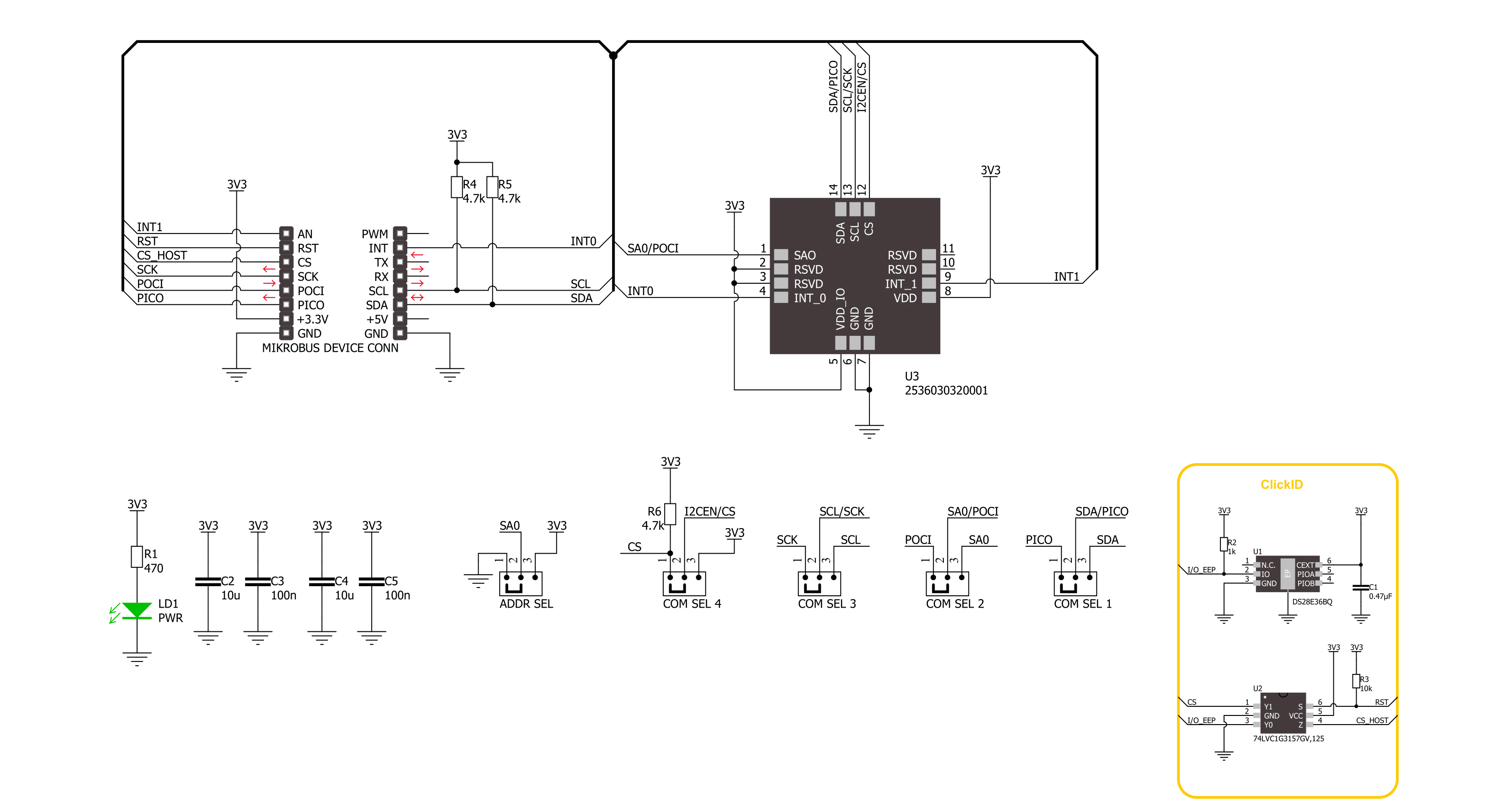
6DOF IMU 21 Click is based on the WSEN-ISDS (2536030320001), 3-axis acceleration, and gyroscope sensor from Würth Elektronik. This sensor embodies the MEMS-based capacitive sensing technology, which is crucial for accurately monitoring motion and orientation. It's specially made to accommodate a variety of application-specific functionalities, such as detecting free-fall events, responding to wake-up signals, recognizing tap gestures, and identifying different states of activity and motion. Additionally, it's capable of tilt and orientation detection, which is crucial for dynamic positioning tasks. The sensor provides this wealth of information through a fully calibrated 16-bit digital output, ensuring high precision and reliability in data capture. This sensor supports acceleration ranges from ±2g to ±16g, and gyroscope ranges from ±125dps to ±2000dps. This
allows for application in a wide range of motion-sensitive tasks. Furthermore, the sensor has an impressive output data rate of up to 6.6kHz, enabling it to track rapid movements seamlessly. An embedded temperature sensor adds another utility layer, offering environmental monitoring alongside motion tracking. With support for both I2C and SPI digital communication interfaces, the Click board offers flexible connectivity options, making it an excellent choice for projects in localization and navigation, industrial tool and equipment optimization, antenna and platform stabilization, industrial IoT innovations, as well as robotics, drones, and automation systems.
As mentioned, the 6DOF IMU 21 Click supports both I2C and SPI interfaces. Users can select the desired communication protocol by placing SMD jumpers on the COMM SEL section, ensuring all
jumpers align on the same side to avoid potential issues. For I2C usage, the device allows the adjustment of its I2C slave address's least significant bit via an SMD jumper marked as ADDR SEL. This Click board™ also possesses two interrupt pins routed to the I0 and I1 pins on the mikroBUS™ socket. These interrupt pins signal MCU that an event has been sensed, entirely programmed by the user through the I2C/SPI interface. This Click board™ can be operated only with a 3.3V logic voltage level. The board must perform appropriate logic voltage level conversion before using MCUs with different logic levels. Also, it comes equipped with a library containing functions and an example code that can be used as a reference for further development.

Features overview
Development board
Curiosity PIC32 MZ EF development board is a fully integrated 32-bit development platform featuring the high-performance PIC32MZ EF Series (PIC32MZ2048EFM) that has a 2MB Flash, 512KB RAM, integrated FPU, Crypto accelerator, and excellent connectivity options. It includes an integrated programmer and debugger, requiring no additional hardware. Users can expand
functionality through MIKROE mikroBUS™ Click™ adapter boards, add Ethernet connectivity with the Microchip PHY daughter board, add WiFi connectivity capability using the Microchip expansions boards, and add audio input and output capability with Microchip audio daughter boards. These boards are fully integrated into PIC32’s powerful software framework, MPLAB Harmony,
which provides a flexible and modular interface to application development a rich set of inter-operable software stacks (TCP-IP, USB), and easy-to-use features. The Curiosity PIC32 MZ EF development board offers expansion capabilities making it an excellent choice for a rapid prototyping board in Connectivity, IOT, and general-purpose applications.

Microcontroller Overview
MCU Card / MCU

Architecture
PIC32
MCU Memory (KB)
2048
Silicon Vendor
Microchip
Pin count
100
RAM (Bytes)
524288
Used MCU Pins
mikroBUS™ mapper
Take a closer look
Click board™ Schematic
Step by step
Project assembly

Start by selecting your development board and Click board™. Begin with the Curiosity PIC32 MZ EF as your development board.


Software Support
Library Description
This library contains API for 6DOF IMU 21 Click driver.
Key functions:
c6dofimu21_software_reset- This function performs the device software resetc6dofimu21_read_accel_data- This function reads the accelerometer of X, Y, and Z axis relative to standard gravity (mg)c6dofimu21_read_gyro_data- This function reads the angular rate of X, Y, and Z axis in degrees per second (mdps)
Open Source
Code example
The complete application code and a ready-to-use project are available through the NECTO Studio Package Manager for direct installation in the NECTO Studio. The application code can also be found on the MIKROE GitHub account.
/*!
 * @file main.c
 * @brief 6DOF IMU 21 Click example
 *
 * # Description
 * This example demonstrates the use of 6DOF IMU 21 Click board by reading and displaying
 * the accelerometer and gyroscope data (X, Y, and Z axis).
 *
 * The demo application is composed of two sections :
 *
 * ## Application Init
 * Initializes the driver performs the Click default configuration,
 * and checks communication by reading device ID.
 *
 * ## Application Task
 * Reading the accelerometer and gyroscope measurements, results are displayed on the USB UART every second.
 *
 * @author Stefan Ilic
 *
 */

#include "board.h"
#include "log.h"
#include "c6dofimu21.h"

static c6dofimu21_t c6dofimu21;
static log_t logger;

void application_init ( void )
{
    log_cfg_t log_cfg;  /**< Logger config object. */
    c6dofimu21_cfg_t c6dofimu21_cfg;  /**< Click config object. */

    /**
     * Logger initialization.
     * Default baud rate: 115200
     * Default log level: LOG_LEVEL_DEBUG
     * @note If USB_UART_RX and USB_UART_TX
     * are defined as HAL_PIN_NC, you will
     * need to define them manually for log to work.
     * See @b LOG_MAP_USB_UART macro definition for detailed explanation.
     */
    LOG_MAP_USB_UART( log_cfg );
    log_init( &logger, &log_cfg );
    log_info( &logger, " Application Init " );

    // Click initialization.
    c6dofimu21_cfg_setup( &c6dofimu21_cfg );
    C6DOFIMU21_MAP_MIKROBUS( c6dofimu21_cfg, MIKROBUS_1 );
    err_t init_flag = c6dofimu21_init( &c6dofimu21, &c6dofimu21_cfg );
    if ( ( I2C_MASTER_ERROR == init_flag ) || ( SPI_MASTER_ERROR == init_flag ) )
    {
        log_error( &logger, " Communication init." );
        for ( ; ; );
    }

    if ( C6DOFIMU21_ERROR == c6dofimu21_default_cfg ( &c6dofimu21 ) )
    {
        log_error( &logger, " Default configuration." );
        for ( ; ; );
    }

    uint8_t dev_id = 0;
    c6dofimu21_generic_read( &c6dofimu21, C6DOFIMU21_REG_DEVICE_ID, &dev_id, 1 );
    if ( C6DOFIMU21_DEVICE_ID != dev_id )
    {
        log_error( &logger, " Communication error " );
    }
    log_printf( &logger, " Device ID: 0x%.2X \r\n", ( uint16_t ) dev_id );

    log_info( &logger, " Application Task " );
}

void application_task ( void )
{
    c6dofimu21_data_t accel_data;
    c6dofimu21_data_t gyro_data;

    c6dofimu21_read_accel_data( &c6dofimu21, &accel_data );
    c6dofimu21_read_gyro_data( &c6dofimu21, &gyro_data );
    log_printf( &logger, " Accel data | Gyro data \r\n" );
    log_printf( &logger, " X: %.2f mg | %.2f mdps \r\n", accel_data.x_data, gyro_data.x_data );
    log_printf( &logger, " Y: %.2f mg | %.2f mdps \r\n", accel_data.y_data, gyro_data.y_data );
    log_printf( &logger, " Z: %.2f mg | %.2f mdps \r\n", accel_data.z_data, gyro_data.z_data );
    Delay_ms ( 1000 );
}

int main ( void )
{
    /* Do not remove this line or clock might not be set correctly. */
    #ifdef PREINIT_SUPPORTED
    preinit();
    #endif

    application_init( );

    for ( ; ; )
    {
        application_task( );
    }

    return 0;
}

// ------------------------------------------------------------------------ END
Additional Support
Resources
Category:Motion


