Maintain ideal atmospheric conditions with 2SMPB-02E and PIC32MX360F512L
The barometer: An instrument of atmospheric measurement

Published Oct 13, 2023
Click board™
Barometer 6 Click
Dev. board
Explorer 16/32 development board
Compiler
NECTO Studio
MCU
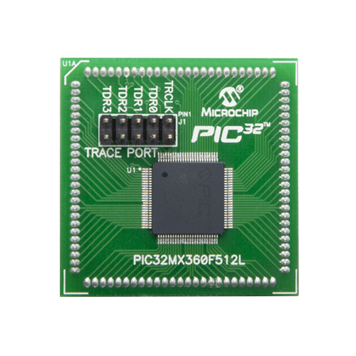
PIC32MX360F512L
Explore the fundamental principles and functions of barometers in measuring atmospheric pressure
A
A
Hardware Overview
How does it work?
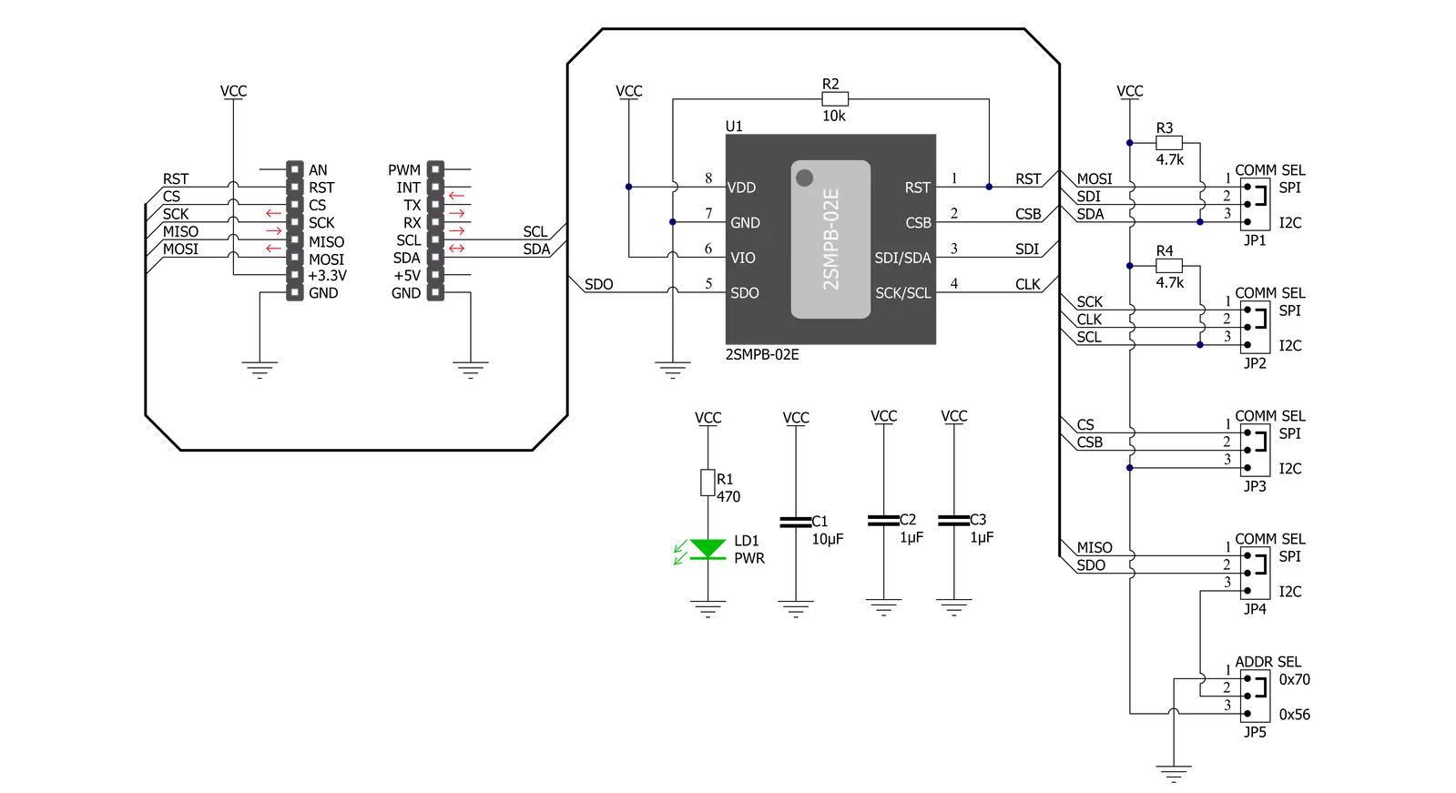
Barometer 6 Click is based on the 2SMPB-02E, a high-accuracy digital barometric air pressure sensor from Omron Electronics, to measure air pressure in a specific environment. The sensor has a calibration parameter for a broader pressure and temperature range. It measures pressure from 30kPa up to 110kPa with an accuracy of ±50Pa over a wide operating temperature range, ideally suited to the harsh environmental conditions in industrial and consumer applications. The 2SMPB-02E features a MEMS chip for sensing air pressure with high accuracy based on the built-in low-noise 24-bit ADC. Individual calibration parameters are
stored in One Time Programmable-ROM (OTP) and are retained when the system is powered down. An integrated temperature compensation circuit helps ensure accurate absolute pressure measurements. Barometer 6 Click allows the use of both I2C and SPI interfaces with a maximum frequency of 3.4MHz for I2C and 10MHz for SPI communication. The selection can be made by positioning SMD jumpers labeled COMM SEL to an appropriate position. Note that all the jumpers' positions must be on the same side, or the Click board™ may become unresponsive. While the I2C interface is selected, the 2SMPB-02E allows
choosing the least significant bit (LSB) of its I2C slave address using the SMD jumper labeled ADDR SEL. This Click board™ also possesses an additional reset pin, routed to the RST pin on the mikroBUS™ socket used to implement the standard reset function. This Click board™ can be operated only with a 3.3V logic voltage level. The board must perform appropriate logic voltage level conversion before using MCUs with different logic levels. Also, it comes equipped with a library containing functions and an example code that can be used as a reference for further development.


Features overview
Development board
Explorer 16/32 development board is a flexible and convenient development, demonstration, and testing platform for 16-bit PIC24 MCUs, dsPIC® DSCs, and 32-bit PIC32 MCUs from Microchip Technology. It features all the necessary hardware to develop and debug a complete embedded application. The board accepts Processor Plug-In Modules (PIMs) designed for the Explorer 16 or Explorer 16/32 development board for easy device swapping. In addition to the hardware features provided by the board, hardware expansion is possible through the use of PICtail™ Plus
daughter cards and mikroBUS™ accessory boards. Coupled with the integrated PICkit™-On-Board (PKOB), MPLAB ICD In-Circuit Debugger real-time debug facilities enable faster evaluation and prototyping of applications. This development board supports all the Explorer PIMs. However, not all PIMs are supported by the PKOB. To check the list of supported and unsupported PIMs, refer to the PICkit™ On-Board 3 (PKOB3) Support List. For PIMs not on the PKOB3 support list, use the JP1 or J14 connectors to program the device with a newer generation programming tool. Explorer 16/32
development board offers only the main board, allowing customization of the other necessary components. Choose your PIM based on MCUs and DSCs under consideration from a wide range of Processor Plug-In Modules. This board is optimal for customers migrating from Classic Explorer 16 to the new Explorer 16/32 platform, while all the necessary additional components like Processor Plug-In Modules and PICtail™ Plus Daughter Boards are already available.

Microcontroller Overview
MCU Card / MCU
Architecture
PIC32
MCU Memory (KB)
512
Silicon Vendor
Microchip
Pin count
100
RAM (Bytes)
32768
Used MCU Pins
mikroBUS™ mapper
Take a closer look
Click board™ Schematic
Step by step
Project assembly

Start by selecting your development board and Click board™. Begin with the Explorer 16/32 development board as your development board.


Software Support
Library Description
This library contains API for Barometer 6 Click driver.
Key functions:
barometer6_hardware_reset- Barometer 6 hardware reset functionbarometer6_set_mode- Barometer 6 set operation mode functionbarometer6_read_temperature_value- Barometer 6 get temperature value function
Open Source
Code example
The complete application code and a ready-to-use project are available through the NECTO Studio Package Manager for direct installation in the NECTO Studio. The application code can also be found on the MIKROE GitHub account.
/*!
 * @file main.c
 * @brief Barometer6 Click example
 *
 * # Description
 * This is an example that demonstrates the use of the Barometer 6 Click board.
 *
 * The demo application is composed of two sections :
 *
 * ## Application Init
 * Initalizes SPI or I2C driver, applies default settings and reads Chip ID.
 *
 * ## Application Task
 * Demonstrates use of Barometer 6 Click board by reading pressure and temperature data seconds
 * and logging it on the UART terminal.
 *
 * @author Stefan Ilic
 *
 */

#include "board.h"
#include "log.h"
#include "barometer6.h"

static barometer6_t barometer6;
static log_t logger;
static uint8_t dev_id;

void application_init ( void )
{
    log_cfg_t log_cfg;  /**< Logger config object. */
    barometer6_cfg_t barometer6_cfg;  /**< Click config object. */

    /**
     * Logger initialization.
     * Default baud rate: 115200
     * Default log level: LOG_LEVEL_DEBUG
     * @note If USB_UART_RX and USB_UART_TX
     * are defined as HAL_PIN_NC, you will
     * need to define them manually for log to work.
     * See @b LOG_MAP_USB_UART macro definition for detailed explanation.
     */
    LOG_MAP_USB_UART( log_cfg );
    log_init( &logger, &log_cfg );
    log_info( &logger, " Application Init " );

    // Click initialization.
    barometer6_cfg_setup( &barometer6_cfg );
    BAROMETER6_MAP_MIKROBUS( barometer6_cfg, MIKROBUS_1 );
    err_t init_flag  = barometer6_init( &barometer6, &barometer6_cfg );
    if ( ( I2C_MASTER_ERROR == init_flag ) || ( SPI_MASTER_ERROR == init_flag ) )
    {
        log_error( &logger, " Communication init." );
        for ( ; ; );
    }

    barometer6_default_cfg ( &barometer6 );

    barometer6_read_id( &barometer6, &dev_id );
    if ( BAROMETER6_ID_VALUE != dev_id )
    {
        log_printf( &logger, " Device communication Error " );
        for ( ; ; );
    }

    log_printf( &logger, "- - - - - - - - - - - - - - -\r\n" );
    log_printf( &logger, " Device ID : 0x%.2X \r\n", ( uint16_t ) dev_id );
    log_printf( &logger, "- - - - - - - - - - - - - - -\r\n" );

    log_info( &logger, " Application Task " );
}

void application_task ( void )
{
    float pressure;
    float temperature;

    barometer6_read_temperature_value( &barometer6, &temperature );
    barometer6_read_preassure_value( &barometer6, &pressure );

    log_printf( &logger, " Temperature : %.2f C    \r\n", temperature );
    log_printf( &logger, " Pressure    : %.2f mBar \r\n", pressure );
    log_printf( &logger, "- - - - - - - - - - - - - - -\r\n" );

    Delay_ms ( 1000 );
}

int main ( void )
{
    /* Do not remove this line or clock might not be set correctly. */
    #ifdef PREINIT_SUPPORTED
    preinit();
    #endif

    application_init( );

    for ( ; ; )
    {
        application_task( );
    }

    return 0;
}

// ------------------------------------------------------------------------ END
Additional Support
Resources
Category:Pressure


