Experience the future of motion sensing with ICM-20948 and PIC18LF46K42
Unmatched low-power 9DOF motion mastery

Published Aug 13, 2023
Click board™
9DOF 2 Click
Dev. board
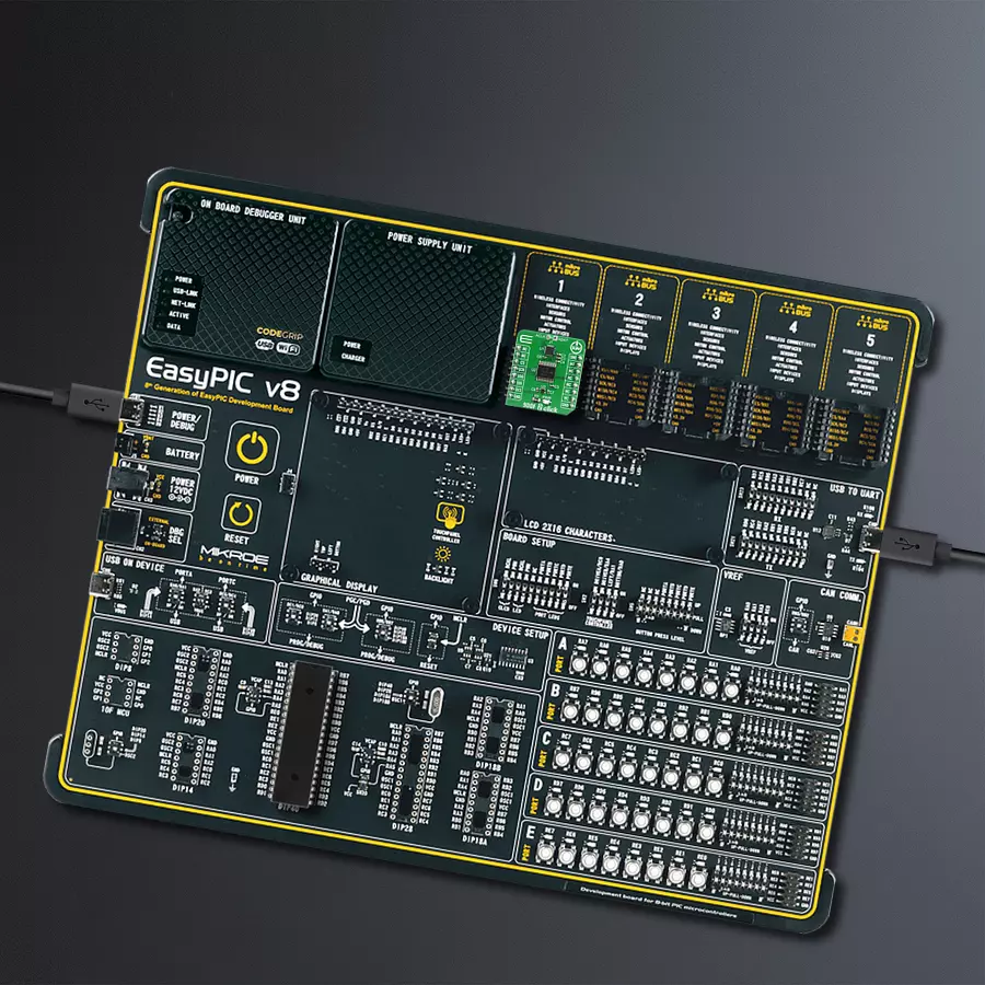
EasyPIC v8
Compiler
NECTO Studio
MCU
PIC18LF46K42
Unlock a realm of possibilities with our 9DOF low-power solution, where motion and magnetometer capabilities unite to redefine what's achievable in efficiency-driven applications without sacrificing the accuracy you demand
A
A
Hardware Overview
How does it work?
9DOF 2 Click is based on the ICM-20948, a high performance, 9-axis MotionTracking™ IC from TDK Invensense. ICM-20948 also supports an auxiliary I2C interface to external sensors, which offers greater system flexibility. The output of each MEMS is processed and digitized by a separate sigma-delta 16-bit A/D converter (ADC). Three-axis gyroscope MEMS can be programmed to measure the rotation about each axis in four different ranges of rotational speed (degrees per angle, DPS): ±250, ±500, ±1000, and ±2000. Three-axis accelerometer MEMS can be programmed to measure the acceleration along each axis in four different acceleration ranges: ±2g, ±4g, ±8g, and ±16g. Three-axis magnetometer can do a full-scale measurement of ±4900 µT. Interrupt functionality is configured via the Interrupt Configuration register. Configurable items include the INT
pin configuration, the interrupt latching and clearing method, and triggers for the interrupt. The interrupt is routed to the INT pin of the mikroBUS™. A FIFO buffer helps to reduce the processing load further, offering temporary storage for the output data. The ICM-20948 contains a FIFO of size 512 bytes (FIFO size will vary depending on the DMP feature-set) accessible via the Serial Interface. The FIFO configuration register determines which data is written into the FIFO. Possible choices include gyro data, accelerometer data, temperature readings, auxiliary sensor readings, and FSYNC input. Synchronization with an external digital signal is possible over the FSYNC pin. This pin is routed to the PWM pin of the mikroBUS™, labeled as SNC. The embedded Digital Motion Processor (DMP) within the ICM-20948 offloads computation of
motion processing algorithms from the host processor. The DMP acquires data from accelerometers, gyroscopes, and additional third-party sensors such as magnetometers and processes the data. The resulting data can be read from the FIFO. The DMP has access to the external pins, which can be used for generating interrupts. ICM-20948 supports SPI and I2C communication interfaces, but only the SPI interface is used on the 9DOF 2 Click. The TXB0108 bidirectional voltage level translator converts the voltage level between ICM-20948 and 3.3V MCU. This Click Board™ uses only the SPI communication interface. It is designed to be operated only with 3.3V logic levels. A proper logic voltage level conversion should be performed before the Click board™ is used with MCUs with logic levels of 5V.


Features overview
Development board
EasyPIC v8 is a development board specially designed for the needs of rapid development of embedded applications. It supports many high pin count 8-bit PIC microcontrollers from Microchip, regardless of their number of pins, and a broad set of unique functions, such as the first-ever embedded debugger/programmer. The development board is well organized and designed so that the end-user has all the necessary elements, such as switches, buttons, indicators, connectors, and others, in one place. Thanks to innovative manufacturing technology, EasyPIC v8 provides a fluid and immersive working experience, allowing access anywhere and under any
circumstances at any time. Each part of the EasyPIC v8 development board contains the components necessary for the most efficient operation of the same board. In addition to the advanced integrated CODEGRIP programmer/debugger module, which offers many valuable programming/debugging options and seamless integration with the Mikroe software environment, the board also includes a clean and regulated power supply module for the development board. It can use a wide range of external power sources, including a battery, an external 12V power supply, and a power source via the USB Type-C (USB-C) connector.
Communication options such as USB-UART, USB DEVICE, and CAN are also included, including the well-established mikroBUS™ standard, two display options (graphical and character-based LCD), and several different DIP sockets. These sockets cover a wide range of 8-bit PIC MCUs, from the smallest PIC MCU devices with only eight up to forty pins. EasyPIC v8 is an integral part of the Mikroe ecosystem for rapid development. Natively supported by Mikroe software tools, it covers many aspects of prototyping and development thanks to a considerable number of different Click boards™ (over a thousand boards), the number of which is growing every day.

Microcontroller Overview
MCU Card / MCU
Architecture
PIC
MCU Memory (KB)
64
Silicon Vendor
Microchip
Pin count
40
RAM (Bytes)
4096
Used MCU Pins
mikroBUS™ mapper
Take a closer look
Click board™ Schematic

Step by step
Project assembly

Start by selecting your development board and Click board™. Begin with the EasyPIC v8 as your development board.


Track your results in real time
Application Output
1. Application Output - In Debug mode, the 'Application Output' window enables real-time data monitoring, offering direct insight into execution results. Ensure proper data display by configuring the environment correctly using the provided tutorial.

2. UART Terminal - Use the UART Terminal to monitor data transmission via a USB to UART converter, allowing direct communication between the Click board™ and your development system. Configure the baud rate and other serial settings according to your project's requirements to ensure proper functionality. For step-by-step setup instructions, refer to the provided tutorial.

3. Plot Output - The Plot feature offers a powerful way to visualize real-time sensor data, enabling trend analysis, debugging, and comparison of multiple data points. To set it up correctly, follow the provided tutorial, which includes a step-by-step example of using the Plot feature to display Click board™ readings. To use the Plot feature in your code, use the function: plot(*insert_graph_name*, variable_name);. This is a general format, and it is up to the user to replace 'insert_graph_name' with the actual graph name and 'variable_name' with the parameter to be displayed.

Software Support
Library Description
This library contains API for 9DOF 2 Click driver.
Key functions:
c9dof2_power- Turns the device on or offc9dof2_read_gyroscope- This function is used to read gyroscope datac9dof2_read_accelerometer- This function is used to read accelerometer data
Open Source
Code example
The complete application code and a ready-to-use project are available through the NECTO Studio Package Manager for direct installation in the NECTO Studio. The application code can also be found on the MIKROE GitHub account.
/*!
 * \file
 * \brief 9dof2 Click example
 *
 * # Description
 * This example demonstrates the use of 9DOF 2 Click board.
 *
 * The demo application is composed of two sections :
 *
 * ## Application Init
 * Initalizes SPI and device drivers, performs safety check,
 * applies default configuration and writes an initial log.
 *
 * ## Application Task
 * Reads the angular and acceleration rates and displays the values of X, Y, and Z axis
 * on the USB UART each second.
 *
 * \author MikroE Team
 *
 */
// ------------------------------------------------------------------- INCLUDES

#include "board.h"
#include "log.h"
#include "c9dof2.h"

// ------------------------------------------------------------------ VARIABLES

static c9dof2_t c9dof2;
static log_t logger;

uint8_t id_val;
float x_accel;
float y_accel;
float z_accel;
float x_gyro;
float y_gyro;
float z_gyro;

// ------------------------------------------------------ APPLICATION FUNCTIONS

void application_init ( void )
{
    log_cfg_t log_cfg;
    c9dof2_cfg_t cfg;

    /**
     * Logger initialization.
     * Default baud rate: 115200
     * Default log level: LOG_LEVEL_DEBUG
     * @note If USB_UART_RX and USB_UART_TX
     * are defined as HAL_PIN_NC, you will
     * need to define them manually for log to work.
     * See @b LOG_MAP_USB_UART macro definition for detailed explanation.
     */
    LOG_MAP_USB_UART( log_cfg );
    log_init( &logger, &log_cfg );
    log_info( &logger, "---- Application Init ----" );

    //  Click initialization.

    c9dof2_cfg_setup( &cfg );
    C9DOF2_MAP_MIKROBUS( cfg, MIKROBUS_1 );
    c9dof2_init( &c9dof2, &cfg );

    c9dof2_dev_rst( &c9dof2 );
    Delay_ms ( 1000 );

    id_val = c9dof2_read_byte ( &c9dof2, C9DOF2_WHO_AM_I_ICM20948 );

    if ( id_val == C9DOF2_WHO_AM_I_ICM20948_VAL )
    {
        log_printf( &logger, "--------------------\r\n" );
        log_printf( &logger, "   9DOF  2  Click   \r\n" );
        log_printf( &logger, "--------------------\r\n" );
        c9dof2_power ( &c9dof2, C9DOF2_POWER_ON );
    }
    else
    {
        log_printf(  &logger, "--------------------\r\n" );
        log_printf(  &logger, "   FATAL ERROR!!!   \r\n" );
        log_printf(  &logger, "--------------------\r\n" );
        for ( ; ; );
    }

    c9dof2_def_settings( &c9dof2 );

    log_printf(  &logger, "--- Initialised ---\r\n" );
    log_printf(  &logger, "--------------------\r\n" );

    Delay_ms ( 1000 );
}

void application_task ( void )
{
    //  Task implementation.

    c9dof2_angular_rate( &c9dof2, &x_gyro, &y_gyro, &z_gyro );

    log_printf( &logger, "Angular rate: \r\n" );

    log_printf( &logger, "X-axis: %.2f \r\n", x_gyro );

    log_printf( &logger, "Y-axis: %.2f \r\n", y_gyro );

    log_printf( &logger, "Z-axis: %.2f \r\n", z_gyro );

    log_printf( &logger, "---------------------\r\n" );

    c9dof2_acceleration_rate( &c9dof2, &x_accel, &y_accel, &z_accel );

    log_printf( &logger, "Acceleration rate: \r\n" );

    log_printf( &logger, "X-axis: %.2f \r\n", x_accel );

    log_printf( &logger, "Y-axis: %.2f \r\n", y_accel );

    log_printf( &logger, "Z-axis: %.2f \r\n", z_accel );

    log_printf( &logger, "---------------------\r\n" );

    Delay_ms ( 1000 );
}

int main ( void )
{
    /* Do not remove this line or clock might not be set correctly. */
    #ifdef PREINIT_SUPPORTED
    preinit();
    #endif

    application_init( );

    for ( ; ; )
    {
        application_task( );
    }

    return 0;
}


// ------------------------------------------------------------------------ END


