Capture and decode barcodes from various media using the LV30 barcode scanner and PIC18F4620
OEM scan engine for outstanding screen code scanning performance

Published Aug 12, 2024
Click board™
Barcode 3 Click
Dev. board
EasyPIC v8
Compiler
NECTO Studio
MCU
PIC18F4620
Read a wide range of 1D and 2D barcode types, including QR codes, data matrices, and linear barcodes
A
A
Hardware Overview
How does it work?
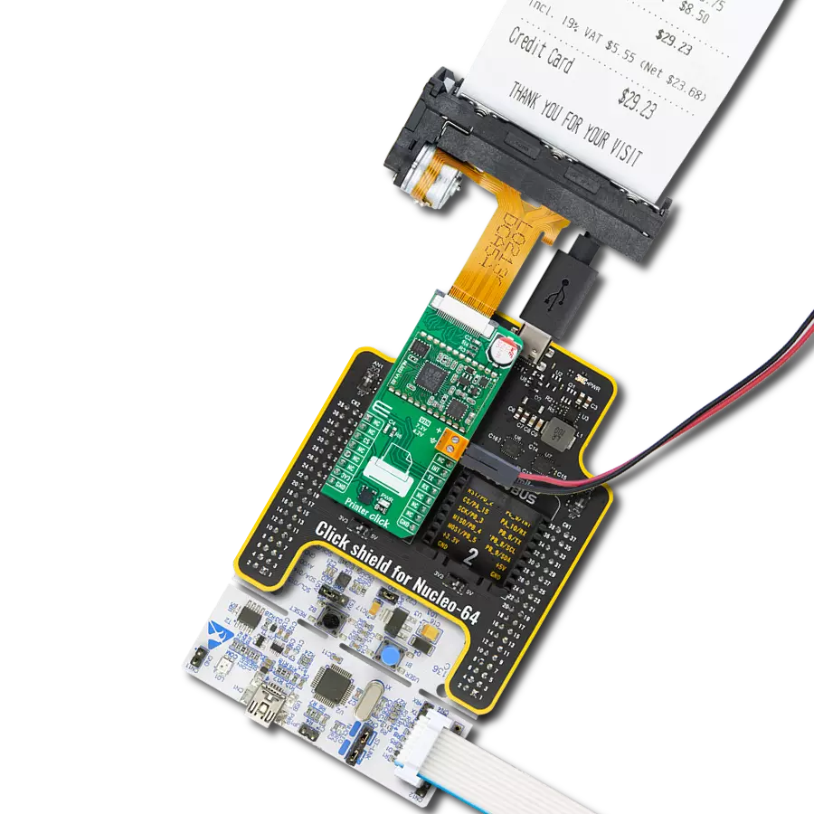
Barcode 3 Click is based on the LV30, an area image engine from Rakinda designed for efficient barcode scanning. This component features a laser aiming system and an LED illumination system, meeting the safety standards of IEC 62471:2006 for LEDs and IEC 60825:2014 for lasers. The LV30 incorporates a CMOS image sensor and a sophisticated image recognition system-on-chip, enabling quick and accurate decoding of barcodes on various media, including paper and magnetic cards. This versatile engine can be easily integrated into OEM equipment such as handheld, portable, or stationary barcode scanners, making it an excellent choice for upgrading from 1D to 2D barcode scanning solutions. The LV30 is equipped with a red LED (wavelength: 625±10nm) for additional lighting, allowing for barcode scanning even in complete darkness, with the option to turn the illumination ON or OFF. It also includes a laser aimer to help users accurately position the barcode within the scanning area, enhancing efficiency. The aiming pattern can be toggled ON or OFF, with the recommendation to keep it on during scanning for
better accuracy. When using the Barcode 3 Click for scanning through a specific surface, it is crucial to ensure proper protection against dust and other contaminants that could degrade the performance of the LV30 module. The surface through which scanning occurs must be made of clear material; it is recommended to use cell-cast plastics or optical glass such as PMMA, ADC, or chemically tempered glass. While the LV30 performs well under ambient light, exposure to high-frequency pulsed light can negatively impact its performance. The illumination LED in the LV30 is bright but designed to be safe under normal usage conditions. Nevertheless, users should avoid direct eye exposure to the beam. The LV30's physical interface includes a 12-pin FPC connector, which allows the Barcode 3 Click to connect to the host MCU using a 12-wire 0.5mm pitch FPC cable. This setup supports communication via the UART interface (the TX and RX pins of the mikroBUS™ socket) or the USB interface. Since the LV30 operates at 3.3V, while using the USB interface, the necessary power supply is provided through an additional
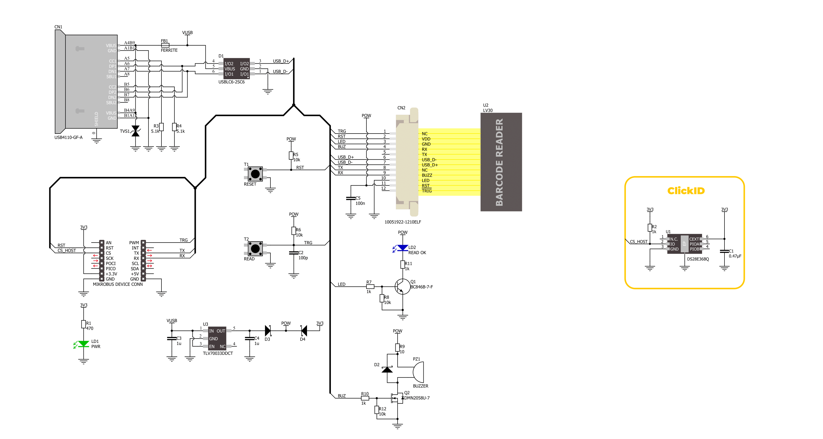
low-dropout (LDO) regulator, the TLV700, which converts the USB voltage level to the required 3.3V for the LV30. The Barcode 3 Click also features several additional components to enhance its functionality. An onboard buzzer provides audible feedback to the user, indicating power-on and successful read statuses. A blue READ OK LED indicator signals a successful barcode read. The READ button, when pressed and released, activates scanning until a barcode is decoded or the decode session timeout expires. This function can also be achieved through the TRG pin on the mikroBUS™ socket. Additionally, the board includes a RESET button for resetting the LV30, which can also be operated via the RST pin on the mikroBUS™ socket. This Click board™ can be operated only with a 3.3V logic voltage level. The board must perform appropriate logic voltage level conversion before using MCUs with different logic levels. Also, it comes equipped with a library containing functions and an example code that can be used as a reference for further development.

Features overview
Development board
EasyPIC v8 is a development board specially designed for the needs of rapid development of embedded applications. It supports many high pin count 8-bit PIC microcontrollers from Microchip, regardless of their number of pins, and a broad set of unique functions, such as the first-ever embedded debugger/programmer. The development board is well organized and designed so that the end-user has all the necessary elements, such as switches, buttons, indicators, connectors, and others, in one place. Thanks to innovative manufacturing technology, EasyPIC v8 provides a fluid and immersive working experience, allowing access anywhere and under any
circumstances at any time. Each part of the EasyPIC v8 development board contains the components necessary for the most efficient operation of the same board. In addition to the advanced integrated CODEGRIP programmer/debugger module, which offers many valuable programming/debugging options and seamless integration with the Mikroe software environment, the board also includes a clean and regulated power supply module for the development board. It can use a wide range of external power sources, including a battery, an external 12V power supply, and a power source via the USB Type-C (USB-C) connector.
Communication options such as USB-UART, USB DEVICE, and CAN are also included, including the well-established mikroBUS™ standard, two display options (graphical and character-based LCD), and several different DIP sockets. These sockets cover a wide range of 8-bit PIC MCUs, from the smallest PIC MCU devices with only eight up to forty pins. EasyPIC v8 is an integral part of the Mikroe ecosystem for rapid development. Natively supported by Mikroe software tools, it covers many aspects of prototyping and development thanks to a considerable number of different Click boards™ (over a thousand boards), the number of which is growing every day.

Microcontroller Overview
MCU Card / MCU
Architecture
PIC
MCU Memory (KB)
64
Silicon Vendor
Microchip
Pin count
40
RAM (Bytes)
3968
Used MCU Pins
mikroBUS™ mapper
Take a closer look
Click board™ Schematic
Step by step
Project assembly

Start by selecting your development board and Click board™. Begin with the EasyPIC v8 as your development board.


Track your results in real time
Application Output
1. Application Output - In Debug mode, the 'Application Output' window enables real-time data monitoring, offering direct insight into execution results. Ensure proper data display by configuring the environment correctly using the provided tutorial.

2. UART Terminal - Use the UART Terminal to monitor data transmission via a USB to UART converter, allowing direct communication between the Click board™ and your development system. Configure the baud rate and other serial settings according to your project's requirements to ensure proper functionality. For step-by-step setup instructions, refer to the provided tutorial.

3. Plot Output - The Plot feature offers a powerful way to visualize real-time sensor data, enabling trend analysis, debugging, and comparison of multiple data points. To set it up correctly, follow the provided tutorial, which includes a step-by-step example of using the Plot feature to display Click board™ readings. To use the Plot feature in your code, use the function: plot(*insert_graph_name*, variable_name);. This is a general format, and it is up to the user to replace 'insert_graph_name' with the actual graph name and 'variable_name' with the parameter to be displayed.

Software Support
Library Description
This library contains API for Barcode 3 Click driver.
Key functions:
barcode3_generic_read- This function reads a desired number of data bytes by using UART serial interface.barcode3_start_scanning- This function starts the barcode scanning by setting the TRG pin to low logic state.barcode3_stop_scanning- This function stops the barcode scanning by setting the TRG pin to high logic state.
Open Source
Code example
The complete application code and a ready-to-use project are available through the NECTO Studio Package Manager for direct installation in the NECTO Studio. The application code can also be found on the MIKROE GitHub account.
/*!
 * @file main.c
 * @brief Barcode 3 Click Example.
 *
 * # Description
 * This example demonstrates the use of the Barcode 3 Click board by scanning
 * and displaying the content of a barcode or QR Code.
 *
 * The demo application is composed of two sections :
 *
 * ## Application Init
 * Initializes the driver, stops scanning and resets the barcode device.
 *
 * ## Application Task
 * Triggers scanning and waits up to 3 seconds for the barcode to be detected.
 * If a barcode or QR Code is detected, it displays its content on the USB UART.
 *
 * ## Additional Function
 * - static void barcode3_clear_app_buf ( void )
 * - static void barcode3_log_app_buf ( void )
 * - static err_t barcode3_process ( barcode3_t *ctx )
 *
 * @author Stefan Filipovic
 *
 */

#include "board.h"
#include "log.h"
#include "barcode3.h"

// Application buffer size
#define APP_BUFFER_SIZE             500
#define PROCESS_BUFFER_SIZE         200

static barcode3_t barcode3;
static log_t logger;

static uint8_t app_buf[ APP_BUFFER_SIZE ] = { 0 };
static int32_t app_buf_len = 0;

/**
 * @brief Barcode 3 clearing application buffer.
 * @details This function clears memory of application buffer and reset its length.
 * @note None.
 */
static void barcode3_clear_app_buf ( void );

/**
 * @brief Barcode 3 log application buffer.
 * @details This function logs data from application buffer to USB UART.
 * @note None.
 */
static void barcode3_log_app_buf ( void );

/**
 * @brief Barcode 3 data reading function.
 * @details This function reads data from device and concatenates data to application buffer.
 * @param[in] ctx : Click context object.
 * See #barcode3_t object definition for detailed explanation.
 * @return @li @c  0 - Read some data.
 *         @li @c -1 - Nothing is read.
 * See #err_t definition for detailed explanation.
 * @note None.
 */
static err_t barcode3_process ( barcode3_t *ctx );

void application_init ( void )
{
    log_cfg_t log_cfg;  /**< Logger config object. */
    barcode3_cfg_t barcode3_cfg;  /**< Click config object. */

    /**
     * Logger initialization.
     * Default baud rate: 115200
     * Default log level: LOG_LEVEL_DEBUG
     * @note If USB_UART_RX and USB_UART_TX
     * are defined as HAL_PIN_NC, you will
     * need to define them manually for log to work.
     * See @b LOG_MAP_USB_UART macro definition for detailed explanation.
     */
    LOG_MAP_USB_UART( log_cfg );
    log_init( &logger, &log_cfg );
    log_info( &logger, " Application Init " );

    // Click initialization.
    barcode3_cfg_setup( &barcode3_cfg );
    BARCODE3_MAP_MIKROBUS( barcode3_cfg, MIKROBUS_1 );
    if ( UART_ERROR == barcode3_init( &barcode3, &barcode3_cfg ) )
    {
        log_error( &logger, " Communication init." );
        for ( ; ; );
    }
    barcode3_stop_scanning ( &barcode3 );
    barcode3_reset_device ( &barcode3 );
    log_info( &logger, " Application Task " );
}

void application_task ( void )
{
    uint16_t timeout = 0;
    log_printf( &logger, "\r\n------- SCAN START ------\r\n" );
    barcode3_start_scanning ( &barcode3 );
    while ( ++timeout < 3000 )
    {
        if ( BARCODE3_OK == barcode3_process( &barcode3 ) )
        {
            barcode3_log_app_buf( );
            barcode3_clear_app_buf( );
            Delay_10ms ( );
            while ( BARCODE3_OK == barcode3_process( &barcode3 ) )
            {
                barcode3_log_app_buf( );
                barcode3_clear_app_buf( );
                Delay_10ms ( );
            }
            break;
        }
        Delay_1ms ( );
    }
    log_printf( &logger, "------- SCAN STOP -------\r\n" );
    barcode3_stop_scanning ( &barcode3 );
    Delay_ms ( 1000 );
    Delay_ms ( 1000 );
    Delay_ms ( 1000 );
}

int main ( void )
{
    /* Do not remove this line or clock might not be set correctly. */
    #ifdef PREINIT_SUPPORTED
    preinit();
    #endif

    application_init( );

    for ( ; ; )
    {
        application_task( );
    }

    return 0;
}

static void barcode3_clear_app_buf ( void )
{
    memset( app_buf, 0, app_buf_len );
    app_buf_len = 0;
}

static void barcode3_log_app_buf ( void )
{
    for ( int32_t buf_cnt = 0; buf_cnt < app_buf_len; buf_cnt++ )
    {
        log_printf( &logger, "%c", app_buf[ buf_cnt ] );
    }
}

static err_t barcode3_process ( barcode3_t *ctx )
{
    uint8_t rx_buf[ PROCESS_BUFFER_SIZE ] = { 0 };
    int32_t overflow_bytes = 0;
    int32_t rx_cnt = 0;
    int32_t rx_size = barcode3_generic_read( ctx, rx_buf, PROCESS_BUFFER_SIZE );
    if ( ( rx_size > 0 ) && ( rx_size <= APP_BUFFER_SIZE ) )
    {
        if ( ( app_buf_len + rx_size ) > APP_BUFFER_SIZE )
        {
            overflow_bytes = ( app_buf_len + rx_size ) - APP_BUFFER_SIZE;
            app_buf_len = APP_BUFFER_SIZE - rx_size;
            memmove ( app_buf, &app_buf[ overflow_bytes ], app_buf_len );
            memset ( &app_buf[ app_buf_len ], 0, overflow_bytes );
        }
        for ( rx_cnt = 0; rx_cnt < rx_size; rx_cnt++ )
        {
            if ( rx_buf[ rx_cnt ] )
            {
                app_buf[ app_buf_len++ ] = rx_buf[ rx_cnt ];
            }
        }
        return BARCODE3_OK;
    }
    return BARCODE3_ERROR;
}

// ------------------------------------------------------------------------ END