Provide accurate detection of lightning activity with AS3935 and PIC32MZ2048EFM100
Experience the power of ThunderSense!

Published Feb 01, 2024
Click board™
Thunder Click
Dev. board
Curiosity PIC32 MZ EF
Compiler
NECTO Studio
MCU
PIC32MZ2048EFM100
Detect the presence and proximity of potentially dangerous lightning activity in the surrounding area
A
A
Hardware Overview
How does it work?
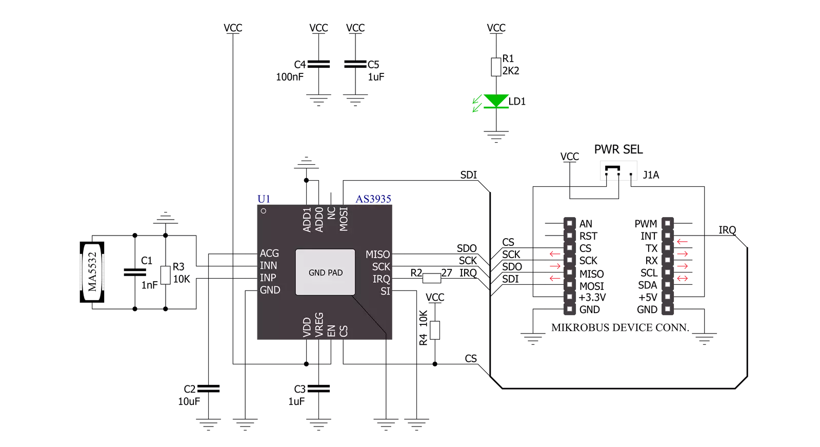
Thunder Click is based on the AS3935, a programmable fully integrated lightning sensor from ams AG that detects the approach of potentially hazardous lightning activity with a sensitive coil antenna, and the MA5532 from Coilcraft. The embedded lightning algorithm checks the incoming signal pattern to reject the potential manufactured disturbers, provides information on the noise level, and informs the host MCU in case of high noise conditions. If the signal is classified as a manufactured disturber, the event is rejected, and the sensor automatically returns to listening mode. Still, if the event is classified as a lightning strike, the statistical distance estimation block evaluates the distance to the head of the storm. The MA5532 external antenna is directly connected to the AS3935's Analog Front-end (AFE), which amplifies
and demodulates the received signal. The watchdog continuously monitors the output of the AFE and alerts the integrated lightning algorithm block in the event of an incoming signal. The embedded hardwired distance estimation algorithm of the AS3935 issues an interrupt on the IRQ pin, routed to the INT pin of the mikroBUS™ socket, every time lightning is detected. The estimated distance, displayed in the distance estimation register, does not represent the distance to the single lightning but the estimated distance to the storm's leading edge. Besides detecting potentially hazardous lightning activity, this Click board™ also provides information on the estimated distance to the storm's center on the noise level. The AS3935 can detect lightning up to 40km away with an accuracy of 1km to the storm front with a sensitive
antenna tuned to pick up lightning events in the 500kHz band. The AS3935 lightning sensor communicates with MCU using the SPI serial interface with a maximum SPI frequency of 2MHz. Note that the clock operation frequency of the SPI should not be identical to the resonance frequency of the antenna (500kHz) to minimize the onboard noise. This Click board™ can operate with either 3.3V or 5V logic voltage levels selected via the PWR SEL jumper. This way, both 3.3V and 5V capable MCUs can use the communication lines properly. However, the Click board™ comes equipped with a library containing easy-to-use functions and an example code that can be used, as a reference, for further development.

Features overview
Development board
Curiosity PIC32 MZ EF development board is a fully integrated 32-bit development platform featuring the high-performance PIC32MZ EF Series (PIC32MZ2048EFM) that has a 2MB Flash, 512KB RAM, integrated FPU, Crypto accelerator, and excellent connectivity options. It includes an integrated programmer and debugger, requiring no additional hardware. Users can expand
functionality through MIKROE mikroBUS™ Click™ adapter boards, add Ethernet connectivity with the Microchip PHY daughter board, add WiFi connectivity capability using the Microchip expansions boards, and add audio input and output capability with Microchip audio daughter boards. These boards are fully integrated into PIC32’s powerful software framework, MPLAB Harmony,
which provides a flexible and modular interface to application development a rich set of inter-operable software stacks (TCP-IP, USB), and easy-to-use features. The Curiosity PIC32 MZ EF development board offers expansion capabilities making it an excellent choice for a rapid prototyping board in Connectivity, IOT, and general-purpose applications.

Microcontroller Overview
MCU Card / MCU

Architecture
PIC32
MCU Memory (KB)
2048
Silicon Vendor
Microchip
Pin count
100
RAM (Bytes)
524288
Used MCU Pins
mikroBUS™ mapper
Take a closer look
Click board™ Schematic
Step by step
Project assembly

Start by selecting your development board and Click board™. Begin with the Curiosity PIC32 MZ EF as your development board.


Software Support
Library Description
This library contains API for Thunder Click driver.
Key functions:
thunder_check_interr- This function checks and returns the interrupt valuethunder_get_storm_info- This function gets energy of the single lightning and distance estimation for the head of the stormthunder_read_reg- This function reads the desired number of bytes from the registers
Open Source
Code example
The complete application code and a ready-to-use project are available through the NECTO Studio Package Manager for direct installation in the NECTO Studio. The application code can also be found on the MIKROE GitHub account.
/*!
 * @file
 * @brief Thunder Click example
 *
 * # Description
 * This application detects the presence and proximity of potentially
 * lightning activity and provides estimated distance to the center of the storm.
 * It can also provide information on the noise level.
 *
 * The demo application is composed of two sections :
 *
 * ## Application Init
 * Initializes SPI driver and performs the reset command and RCO calibrate command.
 * Also configures the device for working properly.
 *
 * ## Application Task
 * Checks if the interrupt event has occured (Listening mode) and after that reads
 * the storm information and logs the results on the USB UART.
 *
 * @author MikroE Team
 *
 */

#include "board.h"
#include "log.h"
#include "thunder.h"

static thunder_t thunder;
static log_t logger;

uint8_t storm_mode;
uint32_t storm_energy;
uint8_t storm_distance;

void application_init ( void )
{
    log_cfg_t log_cfg;
    thunder_cfg_t cfg;

    /**
     * Logger initialization.
     * Default baud rate: 115200
     * Default log level: LOG_LEVEL_DEBUG
     * @note If USB_UART_RX and USB_UART_TX
     * are defined as HAL_PIN_NC, you will
     * need to define them manually for log to work.
     * See @b LOG_MAP_USB_UART macro definition for detailed explanation.
     */
    LOG_MAP_USB_UART( log_cfg );
    log_init( &logger, &log_cfg );
    log_info( &logger, " Application Init " );

    // Click initialization.
    thunder_cfg_setup( &cfg );
    THUNDER_MAP_MIKROBUS( cfg, MIKROBUS_1 );
    thunder_init( &thunder, &cfg );

    thunder_default_cfg( &thunder );
    log_info( &logger, " Application Task " );
}

void application_task ( void )
{
    storm_mode = thunder_check_int ( &thunder );

    if ( THUNDER_NOISE_LEVEL_INTERR == storm_mode )
    {
        log_printf( &logger, "Noise level too high\r\n\n" );
    }
    else if ( THUNDER_DISTURBER_INTERR == storm_mode )
    {
        log_printf( &logger, "Disturber detected\r\n\n" );
    }
    else if ( THUNDER_LIGHTNING_INTERR == storm_mode )
    {
        thunder_get_storm_info( &thunder, &storm_energy, &storm_distance );
        log_printf( &logger, "Energy of the single lightning : %lu\r\n", storm_energy );
        log_printf( &logger, "Distance estimation : %u km\r\n\n", ( uint16_t ) storm_distance );
        // Reset configuration to prepare for the next measurement
        thunder_default_cfg( &thunder );
    }
}

int main ( void )
{
    /* Do not remove this line or clock might not be set correctly. */
    #ifdef PREINIT_SUPPORTED
    preinit();
    #endif

    application_init( );

    for ( ; ; )
    {
        application_task( );
    }

    return 0;
}


// ------------------------------------------------------------------------ END
Additional Support
Resources
Category:Miscellaneous