Enable instant data sharing between devices using PN7150 and PIC18LF46K40
NFC: The secret ingredient behind smarter, faster living

Published Oct 18, 2023
Click board™
NFC 2 Click
Dev. board
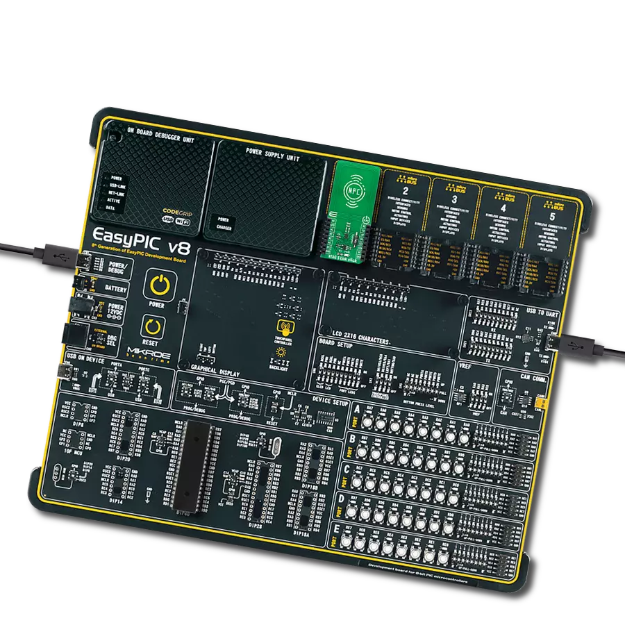
EasyPIC v8
Compiler
NECTO Studio
MCU
PIC18LF46K40
Unleash the power of NFC and explore the boundless innovations and convenience it brings to your digital life, from instant sharing to secure transactions
A
A
Hardware Overview
How does it work?
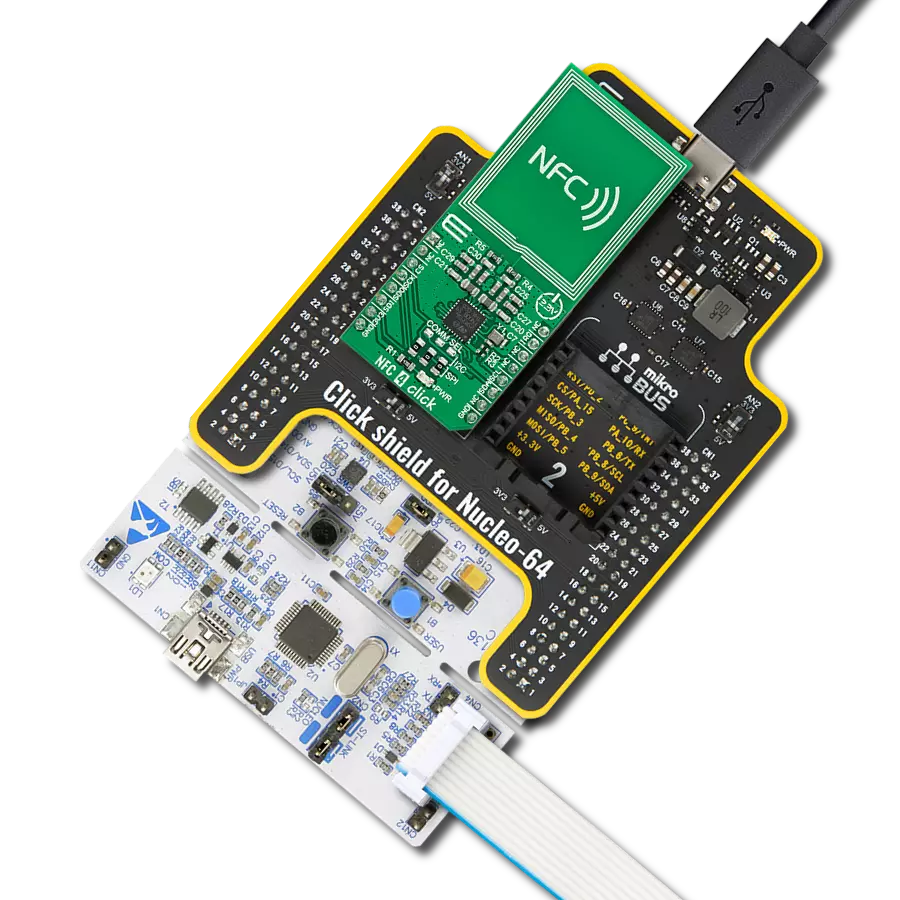
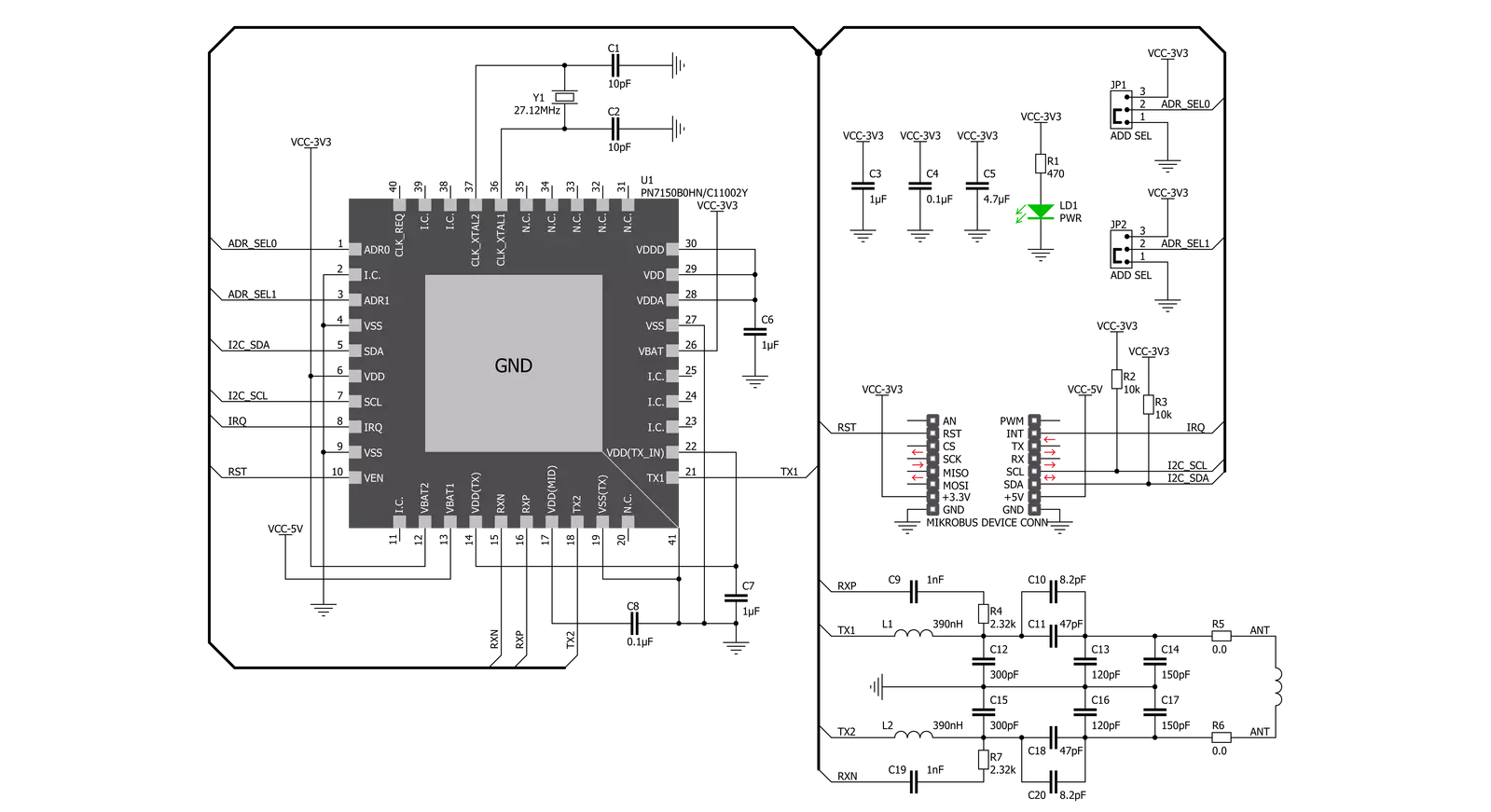
NFC 2 Click is based on the PN7150, a high-performance full NFC solution with integrated firmware and I2C interface designed for contactless communication at 13.56 MHz from NXP Semiconductor. This board fully complies with NFC Forum specifications, which means that you will be able to use the full potential of NFC. It is the ideal solution for rapidly integrating NFC technology in any application, especially those running O/S environments like Linux and Android. It reduces size and cost thanks to embedded NFC firmware providing all NFC protocols as a pre-integrated feature and ultra-low power consumption. The PN7150 embeds a microcontroller core ARM Cortex-M0 loaded with the integrated firmware. It provides an easy integration and validation cycle as all the NFC real-time constraints, protocols, and device discovery are handled internally. The host can configure the PN7150 to notify for a card or peer detection
and start communicating with them. The core microcontroller chip of the PN7150 can run without any external clock (based on an internal oscillator). However, the 13.56MHz RF field carrier accuracy requirements are not compatible with using an internal oscillator. The PN7150 has an external crystal oscillator connected to its XTAL pins. It also has four power states: Monitor, Hard Power Down (HPD), Standby, and Active. The PN7150 will continuously switch between different power states at the application level to optimize the current consumption. The PN7150 is designed to allow the host controller to have full control over its operation, thus, of the power consumption of the PN7150 and the possibility to restrict parts of the PN7150 functionality. More information about these modes user can be found in the attached datasheet. NFC 2 Click communicates with MCU using the standard I2C 2-Wire interface with a clock frequency of up to 100kHz in the Standard,
up to 400kHz in the Fast, and up to 3.4MHz in the High-Speed Mode. The PN7150 also allows the choice of the least significant bit (LSB) of its I2C slave address by positioning SMD jumpers labeled as ADDR SEL to an appropriate position marked as 0 and 1. To enable and ensure data flow control between PN7150 and the host controller, a dedicated interrupt line labeled INT is provided so that the Active state is programmable. It also contains a Reset function and the RF antenna used to communicate over RF with a Tag (Card), Reader/Writer, or Peer device. This Click board™ can be operated only with a 3.3V logic voltage level. The board must perform appropriate logic voltage level conversion before using MCUs with different logic levels. Also, it comes equipped with a library containing functions and an example code that can be used as a reference for further development.


Features overview
Development board
EasyPIC v8 is a development board specially designed for the needs of rapid development of embedded applications. It supports many high pin count 8-bit PIC microcontrollers from Microchip, regardless of their number of pins, and a broad set of unique functions, such as the first-ever embedded debugger/programmer. The development board is well organized and designed so that the end-user has all the necessary elements, such as switches, buttons, indicators, connectors, and others, in one place. Thanks to innovative manufacturing technology, EasyPIC v8 provides a fluid and immersive working experience, allowing access anywhere and under any
circumstances at any time. Each part of the EasyPIC v8 development board contains the components necessary for the most efficient operation of the same board. In addition to the advanced integrated CODEGRIP programmer/debugger module, which offers many valuable programming/debugging options and seamless integration with the Mikroe software environment, the board also includes a clean and regulated power supply module for the development board. It can use a wide range of external power sources, including a battery, an external 12V power supply, and a power source via the USB Type-C (USB-C) connector.
Communication options such as USB-UART, USB DEVICE, and CAN are also included, including the well-established mikroBUS™ standard, two display options (graphical and character-based LCD), and several different DIP sockets. These sockets cover a wide range of 8-bit PIC MCUs, from the smallest PIC MCU devices with only eight up to forty pins. EasyPIC v8 is an integral part of the Mikroe ecosystem for rapid development. Natively supported by Mikroe software tools, it covers many aspects of prototyping and development thanks to a considerable number of different Click boards™ (over a thousand boards), the number of which is growing every day.

Microcontroller Overview
MCU Card / MCU
Architecture
PIC
MCU Memory (KB)
64
Silicon Vendor
Microchip
Pin count
40
RAM (Bytes)
3728
Used MCU Pins
mikroBUS™ mapper
Take a closer look
Click board™ Schematic
Step by step
Project assembly

Start by selecting your development board and Click board™. Begin with the EasyPIC v8 as your development board.


Track your results in real time
Application Output
1. Application Output - In Debug mode, the 'Application Output' window enables real-time data monitoring, offering direct insight into execution results. Ensure proper data display by configuring the environment correctly using the provided tutorial.

2. UART Terminal - Use the UART Terminal to monitor data transmission via a USB to UART converter, allowing direct communication between the Click board™ and your development system. Configure the baud rate and other serial settings according to your project's requirements to ensure proper functionality. For step-by-step setup instructions, refer to the provided tutorial.

3. Plot Output - The Plot feature offers a powerful way to visualize real-time sensor data, enabling trend analysis, debugging, and comparison of multiple data points. To set it up correctly, follow the provided tutorial, which includes a step-by-step example of using the Plot feature to display Click board™ readings. To use the Plot feature in your code, use the function: plot(*insert_graph_name*, variable_name);. This is a general format, and it is up to the user to replace 'insert_graph_name' with the actual graph name and 'variable_name' with the parameter to be displayed.

Software Support
Library Description
This library contains API for NFC 2 Click driver.
Key functions:
nfc2_hw_reset- HW reset function.nfc2_core_set_protocol_config- Set protocol configuration function.nfc2_cmd_card_disconnected- Card disconnected command function.
Open Source
Code example
The complete application code and a ready-to-use project are available through the NECTO Studio Package Manager for direct installation in the NECTO Studio. The application code can also be found on the MIKROE GitHub account.
/*!
 * @file main.c
 * @brief NFC2 Click example
 *
 * # Description
 * This is an example which demonstrates the usage of NFC 2 Click board.
 *
 * The demo application is composed of two sections :
 *
 * ## Application Init
 * Initialization driver enables - I2C,
 * hw reset, reseteting and initialize core, disabling standby mode,
 * starting test procedure, set configuration and start discovery, also write log.
 *
 * ## Application Task
 * NFC 2 Click board can be used for detection of RFiD tag
 * and displays it's value via USART terminal.
 * All data logs write on USB uart changes for every 1 sec.
 *
 * Additional Functions :
 *  -void display_packet ( control_packet_t *ctrl_pck ) - Display packet log data.
 *  -void display_nfc_data ( control_packet_t *ctrl_pck ) - Display packet log data.
 *  -void nfc2_read_nfc_data ( nfc2_t *ctx, control_packet_t *ctrl_pck ) - Read nfc data function.
 *  -void nfc2_test_antenna ( nfc2_t *ctx, control_packet_t *ctrl_pck ) - Testing Antenna function.
 *
 * @author Stefan Ilic
 *
 */

#include "board.h"
#include "log.h"
#include "nfc2.h"

static nfc2_t nfc2;
static log_t logger;
uint8_t n_cnt;

control_packet_t ctrl_pck_data;

/**
 * @brief NFC 2 display packet function.
 * @details This function displays data values.
 */
void display_packet ( control_packet_t *ctrl_pck );

/**
 * @brief NFC 2 display nfc data function.
 * @details This function displays nfc data values.
 */
void display_nfc_data ( control_packet_t *ctrl_pck );

/**
 * @brief NFC 2 read nfc data function.
 * @details This function reads nfc data and displays data.
 */
void nfc2_read_nfc_data ( nfc2_t *ctx, control_packet_t *ctrl_pck );

/**
 * @brief NFC 2  test antena function.
 * @details This function tests antenna and displays data.
 */
void nfc2_test_antenna ( nfc2_t *ctx, control_packet_t *ctrl_pck );

void application_init ( void ) {
    log_cfg_t log_cfg;  /**< Logger config object. */
    nfc2_cfg_t nfc2_cfg;  /**< Click config object. */

    /**
     * Logger initialization.
     * Default baud rate: 115200
     * Default log level: LOG_LEVEL_DEBUG
     * @note If USB_UART_RX and USB_UART_TX
     * are defined as HAL_PIN_NC, you will
     * need to define them manually for log to work.
     * See @b LOG_MAP_USB_UART macro definition for detailed explanation.
     */
    LOG_MAP_USB_UART( log_cfg );
    log_init( &logger, &log_cfg );
    log_info( &logger, " Application Init " );

    // Click initialization.
    nfc2_cfg_setup( &nfc2_cfg );
    NFC2_MAP_MIKROBUS( nfc2_cfg, MIKROBUS_1 );
    err_t init_flag = nfc2_init( &nfc2, &nfc2_cfg );
    if ( I2C_MASTER_ERROR == init_flag ) {
        log_error( &logger, " Application Init Error. " );
        log_info( &logger, " Please, run program again... " );

        for ( ; ; );
    }

    log_printf( &logger, "        HW Reset       \r\n" );
    nfc2_hw_reset( &nfc2 );
    Delay_ms ( 100 );

    log_printf( &logger, "-----------------------\r\n" );
    log_printf( &logger, " Reset and Init. Core  \r\n" );
    nfc2_cmd_core_reset( &nfc2 );
    Delay_ms ( 100 );

    nfc2_read_ctrl_packet_data( &nfc2, &ctrl_pck_data );
    Delay_ms ( 100 );

    nfc2_cmd_core_init( &nfc2 );
    Delay_ms ( 100 );

    nfc2_read_ctrl_packet_data( &nfc2, &ctrl_pck_data );
    Delay_ms ( 100 );
    display_packet( &ctrl_pck_data );

    while ( nfc2_check_irq( &nfc2 ) == NFC2_IRQ_STATE_HIGH );

    log_printf( &logger, "-----------------------\r\n" );
    log_printf( &logger, " Disabling Standby Mode \r\n" );
    nfc2_cmd_disable_standby_mode( &nfc2 );
    Delay_ms ( 100 );

    nfc2_read_ctrl_packet_data( &nfc2, &ctrl_pck_data );
    Delay_ms ( 100 );
    display_packet( &ctrl_pck_data );

    nfc2_test_antenna( &nfc2, &ctrl_pck_data );

    log_printf( &logger, "-----------------------\r\n" );
    log_printf( &logger, "Starting Test Procedure\r\n" );
    nfc2_cmd_test_procedure( &nfc2 );
    Delay_ms ( 100 );

    nfc2_read_ctrl_packet_data( &nfc2, &ctrl_pck_data );
    Delay_ms ( 100 );
    display_packet( &ctrl_pck_data );

    nfc2_hw_reset( &nfc2 );
    Delay_ms ( 100 );

    log_printf( &logger, "-----------------------\r\n" );
    log_printf( &logger, "       NFC Config.     \r\n" );
    nfc2_default_cfg ( &nfc2, &ctrl_pck_data );

    log_printf( &logger, "-----------------------\r\n" );
    log_printf( &logger, "     Discovery Start   \r\n" );
    nfc2_cmd_start_discovery( &nfc2 );
    Delay_ms ( 100 );

    nfc2_read_ctrl_packet_data( &nfc2, &ctrl_pck_data );
    Delay_ms ( 100 );
    display_packet( &ctrl_pck_data );

    log_printf( &logger, "-----------------------\r\n" );
    log_printf( &logger, "-------- START --------\r\n" );
    log_printf( &logger, "-----------------------\r\n" );
    Delay_ms ( 500 );

    log_info( &logger, " Application Task " );
}

void application_task ( void ) {
    while ( nfc2_check_irq( &nfc2 ) == NFC2_IRQ_STATE_HIGH ) {
        nfc2_read_nfc_data ( &nfc2, &ctrl_pck_data );
    }

    while ( nfc2_check_irq( &nfc2 ) == NFC2_IRQ_STATE_LOW );

    log_printf( &logger, "-----------------------\r\n" );
    Delay_ms ( 1000 );
}

int main ( void )
{
    /* Do not remove this line or clock might not be set correctly. */
    #ifdef PREINIT_SUPPORTED
    preinit();
    #endif

    application_init( );

    for ( ; ; )
    {
        application_task( );
    }

    return 0;
}

void display_packet ( control_packet_t *ctrl_pck ) {
    log_printf( &logger, "- - - - - - - - - - - -\r\n" );
    log_printf( &logger, " Message Type   = %d\r\n", ( uint16_t ) ctrl_pck->message_type );
    log_printf( &logger, " Pck Bound Flag = %d\r\n", ( uint16_t ) ctrl_pck->pck_bound_flag );
    log_printf( &logger, " Group Ident    = %d\r\n", ( uint16_t ) ctrl_pck->group_ident );
    log_printf( &logger, " Opcode Ident   = %d\r\n", ( uint16_t ) ctrl_pck->opcode_ident );
    log_printf( &logger, " Payload Length = %d\r\n", ( uint16_t ) ctrl_pck->payload_length );
    log_printf( &logger, "- - - - - - - - - - - -\r\n" );

    for ( n_cnt = 0; n_cnt < ctrl_pck_data.payload_length; n_cnt++ ) {
        log_printf( &logger, " Payload[ %.2d ]  = 0x%.2X\r\n", ( uint16_t ) n_cnt, ( uint16_t ) ( uint16_t ) ctrl_pck_data.payload[ n_cnt ]  );
    }

    log_printf( &logger, "- - - - - - - - - - - -\r\n" );
    memset( ctrl_pck_data.payload, 0x00, 255 );
}

void display_nfc_data ( control_packet_t *ctrl_pck ) {
    log_printf( &logger, "- - - - - - - - - - - -\r\n");
    log_printf( &logger, " Read Block:\r\n");

    for ( n_cnt = 1; n_cnt < ctrl_pck->payload_length - 2; n_cnt++ ) {
        log_printf( &logger, "\t 0x%.2X \r\n", ( uint16_t ) ctrl_pck->payload[ n_cnt ] );
    }
    log_printf( &logger, "\t 0x%.2X \r\n", ( uint16_t ) ctrl_pck->payload[ ctrl_pck->payload_length - 2 ] );

    log_printf( &logger, "- - - - - - - - - - - -\r\n" );
    memset( ctrl_pck->payload, 0x00, 255 );
}

void nfc2_read_nfc_data ( nfc2_t *ctx, control_packet_t *ctrl_pck ){
    nfc2_read_ctrl_packet_data( ctx, ctrl_pck );
    Delay_ms ( 100 );

    nfc2_activate_rmt_mifare_card( ctx );
    Delay_ms ( 100 );
    nfc2_read_ctrl_packet_data( ctx, ctrl_pck );
    Delay_ms ( 10 );

    while ( nfc2_check_irq( ctx ) == NFC2_IRQ_STATE_LOW );

    nfc2_read_ctrl_packet_data( ctx, ctrl_pck );
    nfc2_cmd_authenticate_sector( ctx, 0x30 );
    Delay_ms ( 100 );
    nfc2_read_ctrl_packet_data( ctx, ctrl_pck );
    Delay_ms ( 10 );

    while ( nfc2_check_irq( ctx ) == NFC2_IRQ_STATE_LOW );

    nfc2_read_ctrl_packet_data( ctx, ctrl_pck );
    display_nfc_data( ctrl_pck );
    log_printf( &logger, "    Disconnect Card    \r\n" );
    nfc2_cmd_card_disconnected( ctx );
    Delay_ms ( 10 );
    nfc2_read_ctrl_packet_data( ctx, ctrl_pck );
    Delay_ms ( 10 );

    while ( nfc2_check_irq( ctx ) == NFC2_IRQ_STATE_LOW );

    nfc2_read_ctrl_packet_data( ctx, ctrl_pck );
    Delay_ms ( 100 );
}

void nfc2_test_antenna ( nfc2_t *ctx, control_packet_t *ctrl_pck ) {
    log_printf( &logger, "-----------------------\r\n" );
    log_printf( &logger, "    Testing Antenna    " );
    nfc2_cmd_antenna_test( ctx, 0x01 );
    Delay_ms ( 100 );

    nfc2_read_ctrl_packet_data( ctx, ctrl_pck );
    Delay_ms ( 100 );

    nfc2_cmd_antenna_test( ctx, 0x07 );
    Delay_ms ( 100 );
    nfc2_read_ctrl_packet_data( ctx, ctrl_pck );
    Delay_ms ( 100 );

    nfc2_cmd_antenna_test( ctx, 0x0F );
    Delay_ms ( 100 );
    nfc2_read_ctrl_packet_data( ctx, ctrl_pck );
    Delay_ms ( 100 );
    display_packet( ctrl_pck );
}
// ------------------------------------------------------------------------ END