Modernize your data communication using SC16IS740 and PIC18F4682
Bridging legacy and modern: The RS232 to I2C/SPI solution

Published Nov 01, 2023
Click board™
UART I2C/SPI Click
Dev. board
EasyPIC v8
Compiler
NECTO Studio
MCU
PIC18F4682
Experience the power of data transformation with our solution, seamlessly converting RS232 bus data into the I2C or SPI serial interface of your choice
A
A
Hardware Overview
How does it work?
UART I2C/SPI Click is based on the SC16IS740, an I2C/SPI to UART interface, 64 bytes of transmit and receive FIFOs, and IrDA SIR built-in support, from NXP. This IC bridges the data communication between the two interfaces, offering many additional features, such as the support for the automatic hardware and software flow control, RS-485 support and software reset of the UART. The SC16IS740 can be configured over the SPI or I2C interface, by writing values to a 16C450 compatible set of registers. Maintaining the backward compatibility with the widely popular 16C450 asynchronous communications element (ACE). This allows the software to be easily written or ported from another platform. The second IC provides a physical level conversion for RS-232 communication, as well as the ESD protection within the range of ±15kV. Since the SC16IS740 operates using only TTL/CMOS logic levels, another IC had to be used in order to provide a proper signal conversion on a hardware level. The voltage level of the RS-232 signal can vary between -15V and +15V (-3V to -15V when the line is de-asserted and +3V to +15V when asserted). The MAX3237 IC, a low-power, true RS-232 transceiver from Maxim Integrated is used for the purpose of conditioning
the CMOS/TTL level UART signal from the SC16IS740, into a proper RS-232 signal. All UART lines are driven through this IC, including RXD, TXD, CTS, and RTS lines. After being translated to RS-232 signal levels, these signals are available over the standard RS232 connector (DE-9). The Click board™ is equipped with a number of SMD jumpers. There are five jumpers grouped under the COMM SEL label, used to select one of two available interfaces: SPI, and I2C. By moving all the jumpers at the desired position, the user can select the interface used for the communication with the host MCU. It is advisable to move all the jumpers at once to either left (SPI) or the right (I2C) position. The #RESET pin performs the hardware reset of the SC16IS740 IC. Besides the hardware reset, this device also supports the software reset, by writing a value into the SRESET register. After the Power ON reset, or after a reset pulse is sent over the #RESET pin, it is advised to wait for the external clock oscillator to stabilize. The provided external clock oscillator operates at 1.8432 MHz and takes up to 3ms to stabilize. The #RESET pin is routed to the mikroBUS™ RST pin and it is active LOW. The #INT allows the host MCU to receive an interrupt from the SC16IS740. This pin
allows seven different interrupt sources to generate an interrupt signal. This allows more optimized software (firmware) to be written, as the host MCU does not have to continuously poll the LSR register to see if any interrupt needs to be serviced. However, the software does not have to use interrupts, since each of the interrupt sources will be indicated within the Line Status Register (LSR). The A0/#CS line has two purposes: when the SC16IS740 IC is used in the SPI mode, this pin performs the usual SPI Chip Select function. When used during the I2C mode, this pin determines the I2C address of the device. Therefore, the I2C address of the SC16IS740 IC can be easily changed by applying the specific logic level to this pin. The datasheet of the SC16IS740 offers more information about using and configuring the SC16IS740 IC. However, the Click board™ is supported by a mikroSDK library, offering functions that simplify the prototyping and firmware development. This Click board™ is operated by 3.3V only. To be able to use it with MCUs that use 5V logic level on their communication lines, a proper level-translation circuit should be used.


Features overview
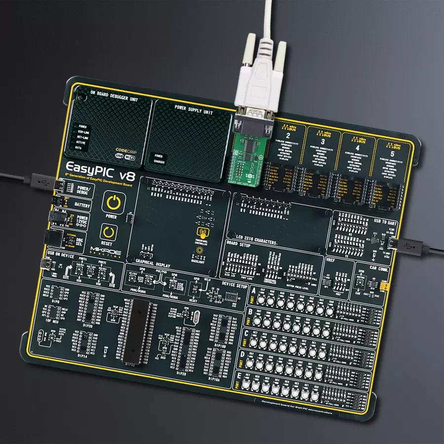
Development board
EasyPIC v8 is a development board specially designed for the needs of rapid development of embedded applications. It supports many high pin count 8-bit PIC microcontrollers from Microchip, regardless of their number of pins, and a broad set of unique functions, such as the first-ever embedded debugger/programmer. The development board is well organized and designed so that the end-user has all the necessary elements, such as switches, buttons, indicators, connectors, and others, in one place. Thanks to innovative manufacturing technology, EasyPIC v8 provides a fluid and immersive working experience, allowing access anywhere and under any
circumstances at any time. Each part of the EasyPIC v8 development board contains the components necessary for the most efficient operation of the same board. In addition to the advanced integrated CODEGRIP programmer/debugger module, which offers many valuable programming/debugging options and seamless integration with the Mikroe software environment, the board also includes a clean and regulated power supply module for the development board. It can use a wide range of external power sources, including a battery, an external 12V power supply, and a power source via the USB Type-C (USB-C) connector.
Communication options such as USB-UART, USB DEVICE, and CAN are also included, including the well-established mikroBUS™ standard, two display options (graphical and character-based LCD), and several different DIP sockets. These sockets cover a wide range of 8-bit PIC MCUs, from the smallest PIC MCU devices with only eight up to forty pins. EasyPIC v8 is an integral part of the Mikroe ecosystem for rapid development. Natively supported by Mikroe software tools, it covers many aspects of prototyping and development thanks to a considerable number of different Click boards™ (over a thousand boards), the number of which is growing every day.

Microcontroller Overview
MCU Card / MCU
Architecture
PIC
MCU Memory (KB)
80
Silicon Vendor
Microchip
Pin count
40
RAM (Bytes)
3328
You complete me!
Accessories
DB9 Cable Female-to-Female (2m) cable is essential for establishing dependable serial data connections between devices. With its DB9 female connectors on both ends, this cable enables a seamless link between various equipment, such as computers, routers, switches, and other serial devices. Measuring 2 meters in length, it offers flexibility in arranging your setup without compromising data transmission quality. Crafted with precision, this cable ensures consistent and reliable data exchange, making it suitable for industrial applications, office environments, and home setups. Whether configuring networking equipment, accessing console ports, or utilizing serial peripherals, this cable's durable construction and robust connectors guarantee a stable connection. Simplify your data communication needs with the 2m DB9 female-to-female cable, an efficient solution designed to meet your serial connectivity requirements easily and efficiently.

Used MCU Pins
mikroBUS™ mapper
Take a closer look
Click board™ Schematic

Step by step
Project assembly

Start by selecting your development board and Click board™. Begin with the EasyPIC v8 as your development board.


Software Support
Library Description
This library contains API for UART I2C/SPI Click driver.
Key functions:
uarti2cspi_advanced_init- Advanced initialization function.uarti2cspi_uart_write_text- Uart write text function.uarti2cspi_uart_read- This function reads one byte from the click module.
Open Source
Code example
The complete application code and a ready-to-use project are available through the NECTO Studio Package Manager for direct installation in the NECTO Studio. The application code can also be found on the MIKROE GitHub account.
/*!
 * \file
 * \brief UARTI2CSPI Click example
 *
 * # Description
 * This example showcases how to initialize, configure and use the UART I2C/SPI Click module.
 * The Click is a I2C/SPI to UART bridge interface. It requires a RS232/485 cable in order to be
 * connected to other Click module or an adapter.
 *
 * The demo application is composed of two sections :
 *
 * ## Application Init
 * Initializes the driver, configures UART, and enables UART interrupts.
 *
 * ## Application Task
 * Depending on the selected mode, it reads all the received data or sends the desired message
 * every 2 seconds.
 *
 * \author MikroE Team
 *
 */
// ------------------------------------------------------------------- INCLUDES

#include "board.h"
#include "log.h"
#include "uarti2cspi.h"

// ------------------------------------------------------------------ VARIABLES

// #define DEMO_APP_TRANSMITTER
#define DEMO_APP_RECEIVER

#define TEXT_TO_SEND    "MikroE - UART I2C/SPI Click\r\n"

static uarti2cspi_t uarti2cspi;
static log_t logger;

// ------------------------------------------------------ APPLICATION FUNCTIONS

void application_init ( void )
{
    log_cfg_t log_cfg;
    uarti2cspi_cfg_t cfg;

    /**
     * Logger initialization.
     * Default baud rate: 115200
     * Default log level: LOG_LEVEL_DEBUG
     * @note If USB_UART_RX and USB_UART_TX
     * are defined as HAL_PIN_NC, you will
     * need to define them manually for log to work.
     * See @b LOG_MAP_USB_UART macro definition for detailed explanation.
     */
    LOG_MAP_USB_UART( log_cfg );
    log_init( &logger, &log_cfg );
    log_info( &logger, "---- Application Init ----" );

    //  Click initialization.

    uarti2cspi_cfg_setup( &cfg );
    UARTI2CSPI_MAP_MIKROBUS( cfg, MIKROBUS_1 );
    uarti2cspi_init( &uarti2cspi, &cfg );
    Delay_ms ( 1000 );

    uarti2cspi_advanced_init( &uarti2cspi, 115200, UARTI2CSPI_UART_8_BIT_DATA,
                                                   UARTI2CSPI_UART_NOPARITY,
                                                   UARTI2CSPI_UART_ONE_STOPBIT );
    Delay_ms ( 100 );
    uarti2cspi_interrupt_enable( &uarti2cspi, UARTI2CSPI_RXD_INT_EN | UARTI2CSPI_THR_EMPTY_INT_EN );

    Delay_ms ( 100 );

#ifdef DEMO_APP_TRANSMITTER
    log_info( &logger, "---- TRANSMITTER MODE ----" );
#endif
#ifdef DEMO_APP_RECEIVER
    log_info( &logger, "---- RECEIVER MODE ----" );
#endif
    Delay_ms ( 1000 );
}

void application_task ( void )
{
#ifdef DEMO_APP_TRANSMITTER
    uarti2cspi_uart_write_text( &uarti2cspi, TEXT_TO_SEND );
    log_info( &logger, "---- The message has been sent ----" );
    Delay_ms ( 1000 );
    Delay_ms ( 1000 );
#endif
#ifdef DEMO_APP_RECEIVER
    if ( uarti2cspi_uart_data_ready( &uarti2cspi ) )
    {
        uint8_t rx_data = uarti2cspi_uart_read( &uarti2cspi );
        log_printf( &logger, "%c", rx_data );
    }
#endif
}

int main ( void )
{
    /* Do not remove this line or clock might not be set correctly. */
    #ifdef PREINIT_SUPPORTED
    preinit();
    #endif

    application_init( );

    for ( ; ; )
    {
        application_task( );
    }

    return 0;
}

// ------------------------------------------------------------------------ END


