Embark on a journey to stability and accuracy with SCR2100-D08, a single-axis gyroscope and PIC18LF47K40
Your path to stability

Published Sep 12, 2023
Click board™
Gyro 8 Click
Dev. board
EasyPIC v8
Compiler
NECTO Studio
MCU
PIC18LF47K40
Navigate with confidence in any environment, thanks to the reliability and precision delivered by our single-axis gyroscope, designed to exceed your expectations
A
A
Hardware Overview
How does it work?
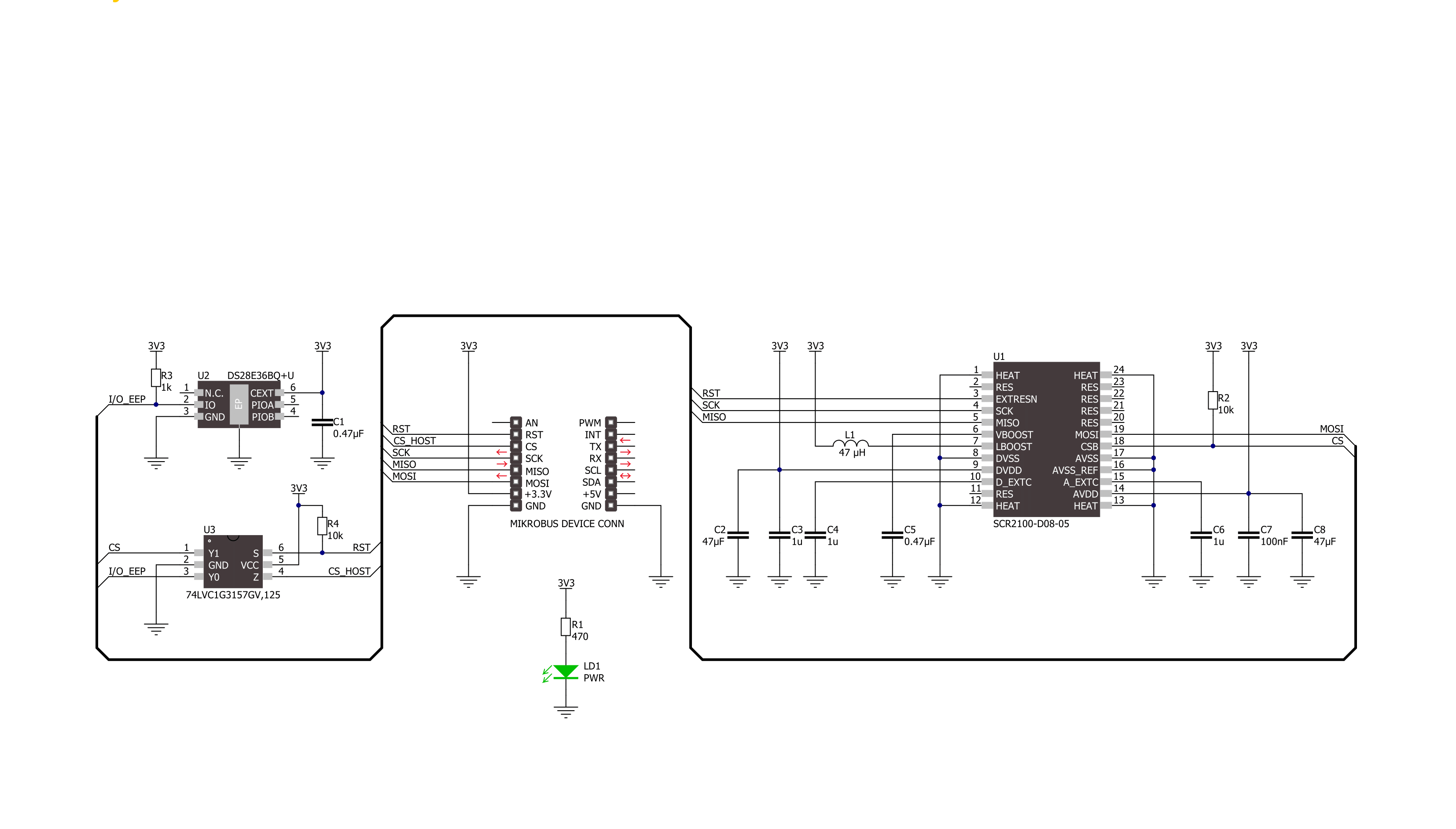
Gyro 8 Click is based on Murata's SCR2100-D08, a high-performance single-axis gyroscope. The SCR2100-D08 is based on proven 3D MEMS technology and highly integrated electronics, offering a performance level characteristic for expensive modules. It consists of an angular rate sensing element and an application-specific integrated circuit (ASIC) used to sense and control the element through an SPI serial interface. Characterized by high stability and reliability, it provides a stable output over ±125°/s X-axis angular rate measurement range. An internal angular rate sensing element consists of moving masses exited to in-plane drive motion. Rotation in a sensitive direction causes out-of-plane movement
that can be measured as capacitance change with the signal conditioning ASIC. It should be noted that the SCR2100-D08 sensor is factory-calibrated, so no separate calibration is required in the application. During manufacturing, the parameters are trimmed during production (sensitivities, offsets, and frequency responses) and stored in non-volatile memory. The parameters are read automatically from the internal non-volatile memory during its Start-up sequence. Gyro 8 Click communicates with MCU through a register-selectable standard SPI interface that enables high clock speed up to 8MHz for optimum performance, supporting the most common SPI mode, SPI Mode 0. Besides the
possibility of controlling and reading gyroscope data via the SPI interface, the SCR2100-D08 also has extensive internal fail-safe diagnostics to detect over-range and possible internal failures and general reset function routed on the RST pin of the mikroBUS™ socket. This Click board™ can be operated only with a 3.3V logic voltage level. The board must perform appropriate logic voltage level conversion before using MCUs with different logic levels. Also, it comes equipped with a library containing functions and an example code that can be used as a reference for further development.


Features overview
Development board
EasyPIC v8 is a development board specially designed for the needs of rapid development of embedded applications. It supports many high pin count 8-bit PIC microcontrollers from Microchip, regardless of their number of pins, and a broad set of unique functions, such as the first-ever embedded debugger/programmer. The development board is well organized and designed so that the end-user has all the necessary elements, such as switches, buttons, indicators, connectors, and others, in one place. Thanks to innovative manufacturing technology, EasyPIC v8 provides a fluid and immersive working experience, allowing access anywhere and under any
circumstances at any time. Each part of the EasyPIC v8 development board contains the components necessary for the most efficient operation of the same board. In addition to the advanced integrated CODEGRIP programmer/debugger module, which offers many valuable programming/debugging options and seamless integration with the Mikroe software environment, the board also includes a clean and regulated power supply module for the development board. It can use a wide range of external power sources, including a battery, an external 12V power supply, and a power source via the USB Type-C (USB-C) connector.
Communication options such as USB-UART, USB DEVICE, and CAN are also included, including the well-established mikroBUS™ standard, two display options (graphical and character-based LCD), and several different DIP sockets. These sockets cover a wide range of 8-bit PIC MCUs, from the smallest PIC MCU devices with only eight up to forty pins. EasyPIC v8 is an integral part of the Mikroe ecosystem for rapid development. Natively supported by Mikroe software tools, it covers many aspects of prototyping and development thanks to a considerable number of different Click boards™ (over a thousand boards), the number of which is growing every day.

Microcontroller Overview
MCU Card / MCU
Architecture
PIC
MCU Memory (KB)
128
Silicon Vendor
Microchip
Pin count
40
RAM (Bytes)
3728
Used MCU Pins
mikroBUS™ mapper
Take a closer look
Click board™ Schematic
Step by step
Project assembly

Start by selecting your development board and Click board™. Begin with the EasyPIC v8 as your development board.


Track your results in real time
Application Output
1. Application Output - In Debug mode, the 'Application Output' window enables real-time data monitoring, offering direct insight into execution results. Ensure proper data display by configuring the environment correctly using the provided tutorial.

2. UART Terminal - Use the UART Terminal to monitor data transmission via a USB to UART converter, allowing direct communication between the Click board™ and your development system. Configure the baud rate and other serial settings according to your project's requirements to ensure proper functionality. For step-by-step setup instructions, refer to the provided tutorial.

3. Plot Output - The Plot feature offers a powerful way to visualize real-time sensor data, enabling trend analysis, debugging, and comparison of multiple data points. To set it up correctly, follow the provided tutorial, which includes a step-by-step example of using the Plot feature to display Click board™ readings. To use the Plot feature in your code, use the function: plot(*insert_graph_name*, variable_name);. This is a general format, and it is up to the user to replace 'insert_graph_name' with the actual graph name and 'variable_name' with the parameter to be displayed.

Software Support
Library Description
This library contains API for Gyro 8 Click driver.
Key functions:
gyro8_read_serial_id- This function reads the serial ID which is laser marked on the sensor lidgyro8_read_temperature- This function reads the temperature measurement in Celsiusgyro8_read_angular_rate- This function reads the angular rate of X-axis in dps.
Open Source
Code example
The complete application code and a ready-to-use project are available through the NECTO Studio Package Manager for direct installation in the NECTO Studio. The application code can also be found on the MIKROE GitHub account.
/*!
 * @file main.c
 * @brief Gyro 8 Click example
 *
 * # Description
 * This example demonstrates the use of Gyro 8 Click board by reading and displaying
 * the temperature and angular rate measurements.
 *
 * The demo application is composed of two sections :
 *
 * ## Application Init
 * Initializes the driver and the Click board, and reads the serial ID number which
 * is marked on the sensor lid.
 *
 * ## Application Task
 * Reads the temperature and angular rate measurements every 100ms and displays the results
 * on the USB UART.
 *
 * @author Stefan Filipovic
 *
 */

#include "board.h"
#include "log.h"
#include "gyro8.h"

static gyro8_t gyro8;
static log_t logger;

void application_init ( void )
{
    log_cfg_t log_cfg;  /**< Logger config object. */
    gyro8_cfg_t gyro8_cfg;  /**< Click config object. */

    /**
     * Logger initialization.
     * Default baud rate: 115200
     * Default log level: LOG_LEVEL_DEBUG
     * @note If USB_UART_RX and USB_UART_TX
     * are defined as HAL_PIN_NC, you will
     * need to define them manually for log to work.
     * See @b LOG_MAP_USB_UART macro definition for detailed explanation.
     */
    LOG_MAP_USB_UART( log_cfg );
    log_init( &logger, &log_cfg );
    log_info( &logger, " Application Init " );

    // Click initialization.
    gyro8_cfg_setup( &gyro8_cfg );
    GYRO8_MAP_MIKROBUS( gyro8_cfg, MIKROBUS_1 );
    if ( SPI_MASTER_ERROR == gyro8_init( &gyro8, &gyro8_cfg ) )
    {
        log_error( &logger, " Communication init." );
        for ( ; ; );
    }

    if ( GYRO8_ERROR == gyro8_default_cfg ( &gyro8 ) )
    {
        log_error( &logger, " Default configuration." );
        for ( ; ; );
    }

    uint32_t serial_id;
    if ( GYRO8_OK == gyro8_read_serial_id ( &gyro8, &serial_id ) )
    {
        log_printf ( &logger, " Serial ID: %lu\r\n", serial_id );
    }

    log_info( &logger, " Application Task " );
}

void application_task ( void )
{
    float temperature, angular_rate;
    if ( GYRO8_OK == gyro8_read_temperature ( &gyro8, &temperature ) )
    {
        log_printf ( &logger, " Temperature: %.2f degC\r\n", temperature );
    }
    if ( GYRO8_OK == gyro8_read_angular_rate ( &gyro8, &angular_rate ) )
    {
        log_printf ( &logger, " Angular rate: %.2f dps\r\n\n", angular_rate );
    }
    Delay_ms ( 100 );
}

int main ( void )
{
    /* Do not remove this line or clock might not be set correctly. */
    #ifdef PREINIT_SUPPORTED
    preinit();
    #endif

    application_init( );

    for ( ; ; )
    {
        application_task( );
    }

    return 0;
}

// ------------------------------------------------------------------------ END


