Upgrade your audio equipment with PCM5142 and PIC18LF27K40
Experience sound at its best
Published Nov 01, 2023
Click board™
Audio DAC Click
Dev. board
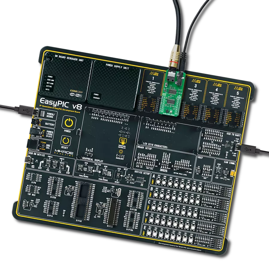
EasyPIC v8
Compiler
NECTO Studio
MCU
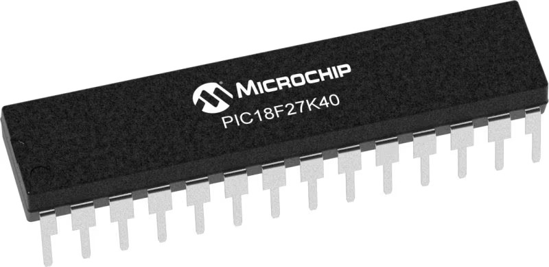
PIC18LF27K40
Elevate your audio quality by converting sound into a premium analog signal, ensuring an exceptional audio playback experience
A
A
Hardware Overview
How does it work?
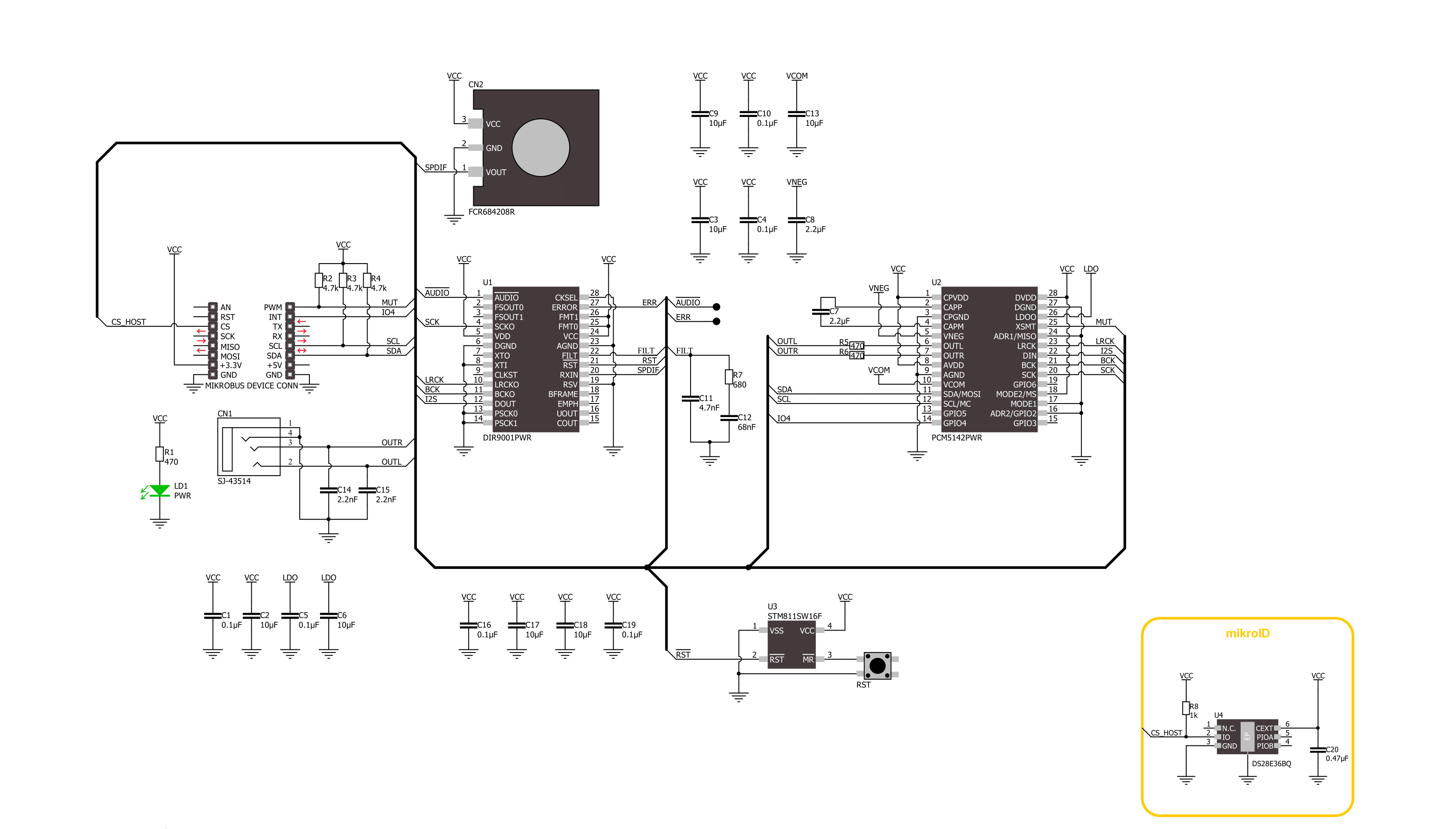
Audio DAC Click is based on a combination of DIR9001 and PCM5142, a digital audio interface receiver and audio stereo DAC from Texas Instruments, suitable for upgrading your audio equipment. The DIR9001 audio receiver can accept signals up to a 108kHz sampling rate at the highest, 24-bit data word, biphase-encoded signal, and complies with the jitter specification IEC60958-3, JEITA CPR1205 (Revised version of EIAJ CP-1201), AES3, and EBUtech3250. These signals are brought to the DIR9001 via an onboard fiber optic S/PDIF connector, better known as Sony/Philips digital interface format, a digital audio interface often used in consumer audio equipment. After receiving the signals, the DIR9001 forwards them for further processing by the stereo audio DAC, the PCM5142, also from Texas Instruments. The PCM5142 has a fully programmable miniDSP core, allowing developers
to integrate filters, dynamic range controls, custom interpolators, and other differentiating features into their applications. It uses the latest generation of TI's advanced segment-DAC architecture to achieve excellent dynamic performance, detailed heights, and an exceptionally good sound stage. Compared with existing DAC technology, the PCM5142 offers up to 20dB lower out-of-band noise, reducing EMI and aliasing in downstream amplifiers/ADCs, and accepts industry-standard audio data formats with 16- to 32-bit data and sample rates up to 384kHz. After stereo DAC processing, the output audio signal is available to users for further use on the 3.5mm-line output audio jack, making it suitable for various multimedia systems, satellite radio, CD and DVD players, and more. The PCM5142 communicates with MCU using the standard I2C 2-Wire data transmission protocol
that supports Standard-Mode (100 kHz) and Fast-Mode (400 kHz) operations. In addition to communication pins, this board has several additional functions, providing users with application flexibility. Besides the I2C signals, the mikroBUS™ also has an auto-mute function routed to the MUT pin on the mikroBUS™ socket to mute the device upon intentional or unintentional power loss, as well as one user-configurable general-purpose pin, the IO4 pin of the mikroBUS™ socket. The onboard button labeled as RST can reset the DIR9001 audio receiver. This Click board™ can be operated only with a 3.3V logic voltage level. The board must perform appropriate logic voltage level conversion before using MCUs with different logic levels. Also, it comes equipped with a library containing functions and an example code that can be used as a reference for further development.

Features overview
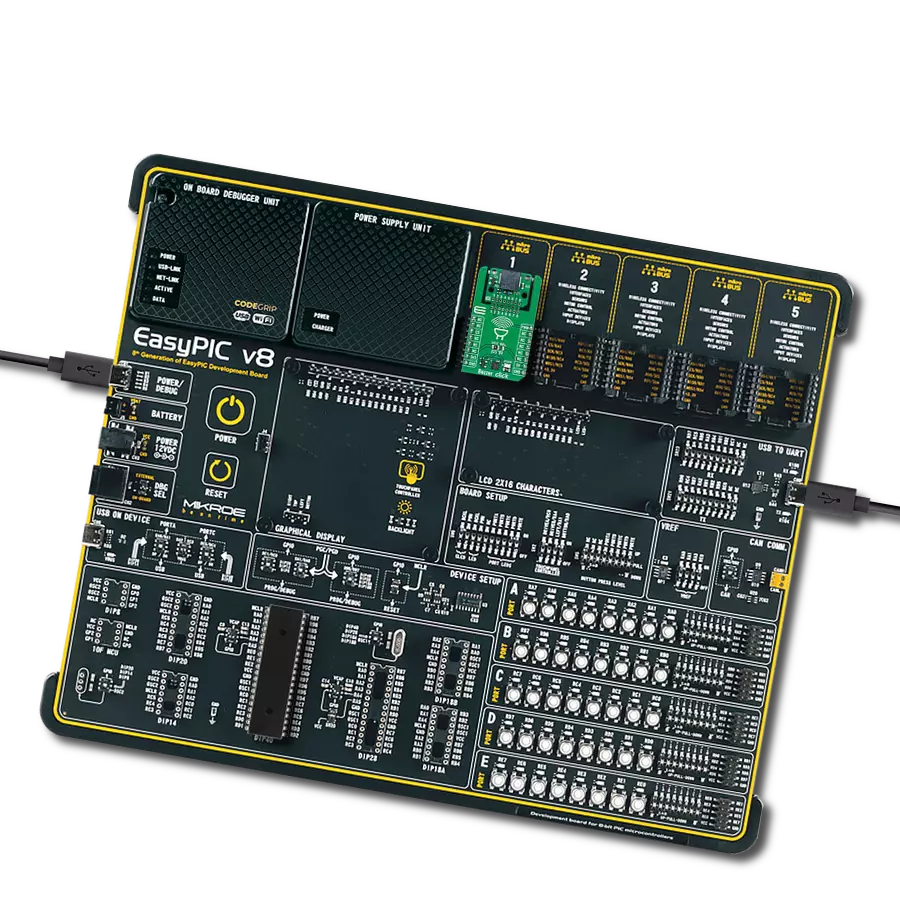
Development board
EasyPIC v8 is a development board specially designed for the needs of rapid development of embedded applications. It supports many high pin count 8-bit PIC microcontrollers from Microchip, regardless of their number of pins, and a broad set of unique functions, such as the first-ever embedded debugger/programmer. The development board is well organized and designed so that the end-user has all the necessary elements, such as switches, buttons, indicators, connectors, and others, in one place. Thanks to innovative manufacturing technology, EasyPIC v8 provides a fluid and immersive working experience, allowing access anywhere and under any
circumstances at any time. Each part of the EasyPIC v8 development board contains the components necessary for the most efficient operation of the same board. In addition to the advanced integrated CODEGRIP programmer/debugger module, which offers many valuable programming/debugging options and seamless integration with the Mikroe software environment, the board also includes a clean and regulated power supply module for the development board. It can use a wide range of external power sources, including a battery, an external 12V power supply, and a power source via the USB Type-C (USB-C) connector.
Communication options such as USB-UART, USB DEVICE, and CAN are also included, including the well-established mikroBUS™ standard, two display options (graphical and character-based LCD), and several different DIP sockets. These sockets cover a wide range of 8-bit PIC MCUs, from the smallest PIC MCU devices with only eight up to forty pins. EasyPIC v8 is an integral part of the Mikroe ecosystem for rapid development. Natively supported by Mikroe software tools, it covers many aspects of prototyping and development thanks to a considerable number of different Click boards™ (over a thousand boards), the number of which is growing every day.

Microcontroller Overview
MCU Card / MCU
Architecture
PIC
MCU Memory (KB)
128
Silicon Vendor
Microchip
Pin count
28
RAM (Bytes)
3728
Used MCU Pins
mikroBUS™ mapper
Take a closer look
Click board™ Schematic
Step by step
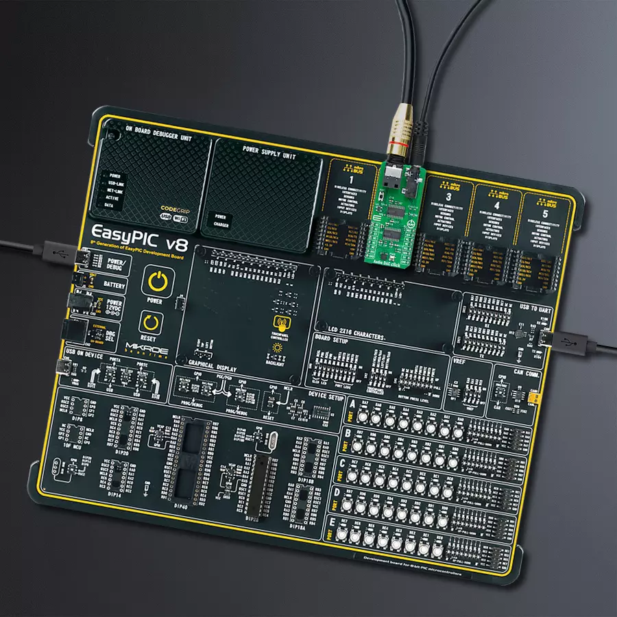
Project assembly

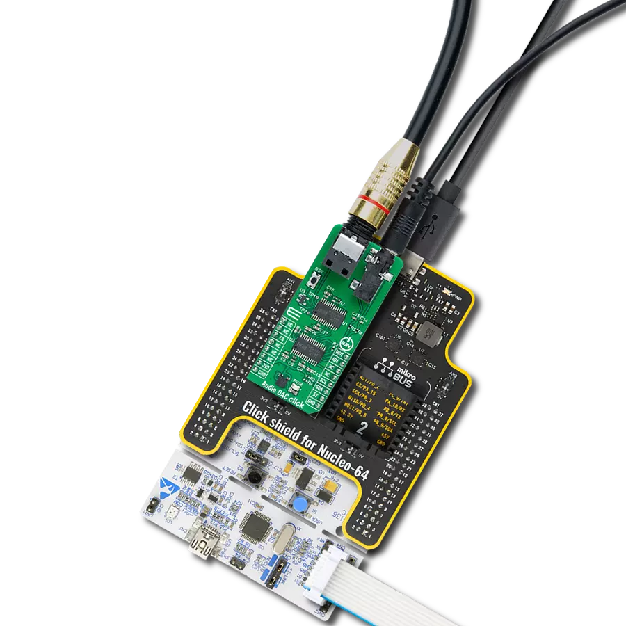
Start by selecting your development board and Click board™. Begin with the EasyPIC v8 as your development board.


Track your results in real time
Application Output
1. Application Output - In Debug mode, the 'Application Output' window enables real-time data monitoring, offering direct insight into execution results. Ensure proper data display by configuring the environment correctly using the provided tutorial.

2. UART Terminal - Use the UART Terminal to monitor data transmission via a USB to UART converter, allowing direct communication between the Click board™ and your development system. Configure the baud rate and other serial settings according to your project's requirements to ensure proper functionality. For step-by-step setup instructions, refer to the provided tutorial.

3. Plot Output - The Plot feature offers a powerful way to visualize real-time sensor data, enabling trend analysis, debugging, and comparison of multiple data points. To set it up correctly, follow the provided tutorial, which includes a step-by-step example of using the Plot feature to display Click board™ readings. To use the Plot feature in your code, use the function: plot(*insert_graph_name*, variable_name);. This is a general format, and it is up to the user to replace 'insert_graph_name' with the actual graph name and 'variable_name' with the parameter to be displayed.

Software Support
Library Description
This library contains API for Audio DAC Click driver.
Key functions:
audiodac_get_gpio4_pin- This function returns the GPIO4 pin logic state. The GPIO4 pin is mapped to auto mute flag output for both L and R channels by defaultaudiodac_volume_control- This function sets the volume level for the selected output channel
Open Source
Code example
The complete application code and a ready-to-use project are available through the NECTO Studio Package Manager for direct installation in the NECTO Studio. The application code can also be found on the MIKROE GitHub account.
/*!
 * @file main.c
 * @brief Audio DAC Click example
 *
 * # Description
 * This example demonstrates the use of Audio DAC Click board by controling the volume
 * level of both output channels.
 *
 * The demo application is composed of two sections :
 *
 * ## Application Init
 * Initializes the driver and performs the Click default configuration.
 *
 * ## Application Task
 * Checks if the auto mute flag is set and then changes the volume level of both output channels
 * every 100ms. All data is being displayed on the USB UART where you can track the program flow.
 *
 * @author Stefan Filipovic
 *
 */

#include "board.h"
#include "log.h"
#include "audiodac.h"

static audiodac_t audiodac;
static log_t logger;

void application_init ( void )
{
    log_cfg_t log_cfg;  /**< Logger config object. */
    audiodac_cfg_t audiodac_cfg;  /**< Click config object. */

    /**
     * Logger initialization.
     * Default baud rate: 115200
     * Default log level: LOG_LEVEL_DEBUG
     * @note If USB_UART_RX and USB_UART_TX
     * are defined as HAL_PIN_NC, you will
     * need to define them manually for log to work.
     * See @b LOG_MAP_USB_UART macro definition for detailed explanation.
     */
    LOG_MAP_USB_UART( log_cfg );
    log_init( &logger, &log_cfg );
    log_info( &logger, " Application Init " );

    // Click initialization.
    audiodac_cfg_setup( &audiodac_cfg );
    AUDIODAC_MAP_MIKROBUS( audiodac_cfg, MIKROBUS_1 );
    if ( I2C_MASTER_ERROR == audiodac_init( &audiodac, &audiodac_cfg ) )
    {
        log_error( &logger, " Communication init." );
        for ( ; ; );
    }

    if ( AUDIODAC_ERROR == audiodac_default_cfg ( &audiodac ) )
    {
        log_error( &logger, " Default configuration." );
        for ( ; ; );
    }

    log_info( &logger, " Application Task " );
}

void application_task ( void )
{
    static uint8_t volume = AUDIODAC_VOLUME_MUTE;
    if ( audiodac_get_gpio4_pin ( &audiodac ) )
    {
        log_printf ( &logger, " Auto mute flag (both L and R channels are auto muted)\r\n" );
        // Wait until the channels are auto unmuted, i.e. until a valid digital signal is received
        while ( audiodac_get_gpio4_pin ( &audiodac ) );
    }
    if ( AUDIODAC_OK == audiodac_volume_control ( &audiodac, AUDIODAC_CHANNEL_BOTH, volume ) )
    {
        log_printf ( &logger, "\r\n Volume: " );
        if ( AUDIODAC_VOLUME_MUTE == volume )
        {
            log_printf ( &logger, "MUTE\r\n" );
            Delay_ms ( 1000 );
            Delay_ms ( 1000 );
            Delay_ms ( 1000 );
        }
        else if ( AUDIODAC_VOLUME_MAX == volume )
        {
            log_printf ( &logger, "MAX\r\n" );
            Delay_ms ( 1000 );
            Delay_ms ( 1000 );
            Delay_ms ( 1000 );
        }
        else
        {
            log_printf ( &logger, "%u\r\n", ( uint16_t ) volume );
            Delay_ms ( 100 );
        }
        volume++;
        if ( volume > AUDIODAC_VOLUME_MAX )
        {
            volume = AUDIODAC_VOLUME_MUTE;
        }
    }
}

int main ( void )
{
    /* Do not remove this line or clock might not be set correctly. */
    #ifdef PREINIT_SUPPORTED
    preinit();
    #endif

    application_init( );

    for ( ; ; )
    {
        application_task( );
    }

    return 0;
}

// ------------------------------------------------------------------------ END