Discover the magic of brushless motor control with MTD6508 and PIC18LF25K40
Harness the speed, tame the power
Published Nov 01, 2023
Click board™
Brushless 22 Click
Dev. board
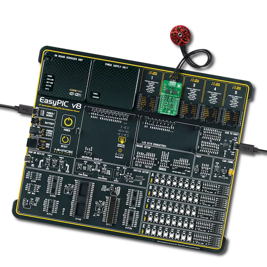
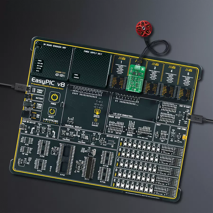
EasyPIC v8
Compiler
NECTO Studio
MCU
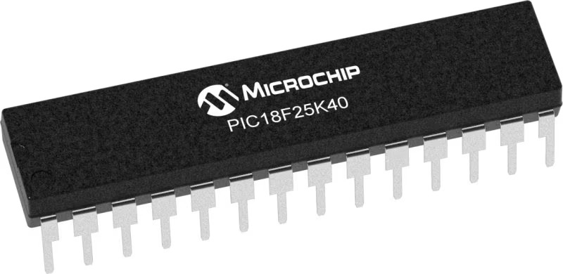
PIC18LF25K40
Upgrade your industry-based application with state-of-the-art brushless motor control. Act now and stay ahead of the curve
A
A
Hardware Overview
How does it work?
Brushless 22 Click is based on the MTD6508, a 3-phase full-wave sensorless driver for brushless DC motors from Microchip Technology. It features a 180° sinusoidal drive, high torque output, and silent drive. CMOS transistors and a synchronous rectification drive type achieve high efficiency and low power consumption. With adaptive features and parameters, the MTD6508 is intended to cover a broad range of motor characteristics, making this Click board™ extremely cost-efficient in fan applications that require low acoustic noise and low mechanical vibration and are highly efficient. This device provides start-up output slew rate and PWM duty cycle control, allowing designers to balance acoustic performance and reliability. The rotational speed of the motor is controlled through the mikroBUS™ PWM signal. When the PWM signal is high, the motor rotates at full speed, and when the PWM signal is low, the MTD6508 outputs are set to a high impedance state, and the motor is stopped. The sinusoidal start-up open-loop phase current amplitude is controlled via the SS pin, routed on the CS pin of the mikroBUS™ socket, which according to its logic state, chooses whether it is defined by the PWM input duty cycle or fixed at 100%. The output
PWM slew rate can be adjusted with the R4 resistor during Start-Up, which is not populated in a default configuration to reduce motor vibration. By default configuration, the output PWM slew rate can be set via the digital potentiometer from Microchip Technology, which establishes communication with the MCU via I2C serial communication. The MCP4661 also allows the choice of the least significant bit (LSB) of its I2C slave address by positioning SMD jumpers labeled as ADDR SEL to an appropriate position marked as 0 and 1. Once the Start-Up open loop is finished, the MTD6508 will automatically switch to a fixed slew rate. When choosing MCP4661 and not R4 for setting the output PWM slew rate, you need to unpopulate the R4 resistor and leave populated R5 and R8. In addition to the output PWM slew rate and its setting method, the user is also given the option of setting the electromechanical coupling coefficient of the motor (also referred to as “motor constant” or “BEMF constant”) via R9 resistor, which is populated in default configuration or by R6 and R7 voltage divider. The MTD6508 defines the BEMF coefficient as the peak value of the phase-to-phase BEMF voltage normalized to the electrical speed of the motor. Choosing MCP4661
and not voltage divider for setting BEMF constant, unpopulate R9 resistor and leave populated R6 and R7. Alongside I2C communication, several GPIO pins connected to the mikroBUS™ socket pins are also used to forward the information to the MCU. The DIR pin, routed on the RST pin of the mikroBUS™ socket, is used to select the direction of motor rotation (clockwise/counterclockwise). The RT pin, routed on the AN pin of the mikroBUS™ socket, adjusts the phase regulation parameters to allow more stability in applications using 3-Phase BLDC motors attached to a light load, while the FG pin routed on the INT pin serves as a rotation speed indicator, gives information about the speed and phase of the motor. With R12 populated, the rotor speed rotation per minute (RPM) has to be multiplied by three because the FG signal frequency will be divided by three. This Click board™ can operate with either 3.3V or 5V logic voltage levels selected via the VCC SEL jumper. This way, both 3.3V and 5V capable MCUs can use the communication lines properly. This Click board™ comes equipped with a library containing easy-to-use functions and an example code that can be used, as a reference, for further development.

Features overview
Development board
EasyPIC v8 is a development board specially designed for the needs of rapid development of embedded applications. It supports many high pin count 8-bit PIC microcontrollers from Microchip, regardless of their number of pins, and a broad set of unique functions, such as the first-ever embedded debugger/programmer. The development board is well organized and designed so that the end-user has all the necessary elements, such as switches, buttons, indicators, connectors, and others, in one place. Thanks to innovative manufacturing technology, EasyPIC v8 provides a fluid and immersive working experience, allowing access anywhere and under any
circumstances at any time. Each part of the EasyPIC v8 development board contains the components necessary for the most efficient operation of the same board. In addition to the advanced integrated CODEGRIP programmer/debugger module, which offers many valuable programming/debugging options and seamless integration with the Mikroe software environment, the board also includes a clean and regulated power supply module for the development board. It can use a wide range of external power sources, including a battery, an external 12V power supply, and a power source via the USB Type-C (USB-C) connector.
Communication options such as USB-UART, USB DEVICE, and CAN are also included, including the well-established mikroBUS™ standard, two display options (graphical and character-based LCD), and several different DIP sockets. These sockets cover a wide range of 8-bit PIC MCUs, from the smallest PIC MCU devices with only eight up to forty pins. EasyPIC v8 is an integral part of the Mikroe ecosystem for rapid development. Natively supported by Mikroe software tools, it covers many aspects of prototyping and development thanks to a considerable number of different Click boards™ (over a thousand boards), the number of which is growing every day.

Microcontroller Overview
MCU Card / MCU
Architecture
PIC
MCU Memory (KB)
32
Silicon Vendor
Microchip
Pin count
28
RAM (Bytes)
2048
You complete me!
Accessories
2207V-2500kV BLDC Motor is an outrunner brushless DC motor with a kV rating of 2500 and an M5 shaft diameter. It is an excellent solution for fulfilling many functions initially performed by brushed DC motors or in RC drones, racing cars, and much more.

Used MCU Pins
mikroBUS™ mapper
Take a closer look
Click board™ Schematic

Step by step
Project assembly

Start by selecting your development board and Click board™. Begin with the EasyPIC v8 as your development board.


Software Support
Library Description
This library contains API for Brushless 22 Click driver.
Key functions:
brushless22_set_slew_rate_resistance- This function sets the slew rate resistance by configuring the onboard digital potentiometerbrushless22_set_duty_cycle- This function sets the PWM duty cycle in percentages ( Range[ 0..1 ] )brushless22_switch_direction- This function switches the direction by toggling the DIR pin state
Open Source
Code example
The complete application code and a ready-to-use project are available through the NECTO Studio Package Manager for direct installation in the NECTO Studio. The application code can also be found on the MIKROE GitHub account.
/*!
 * @file main.c
 * @brief Brushless22 Click example
 *
 * # Description
 * This example demonstrates the use of the Brushless 22 Click board by driving the
 * motor in both directions at different speeds.
 *
 * The demo application is composed of two sections :
 *
 * ## Application Init
 * Initializes the driver and performs the Click default configuration.
 *
 * ## Application Task
 * Controls the motor speed by changing the PWM duty cycle every 500ms.
 * The duty cycle ranges from 0% to 100%. At the minimal speed, the motor switches direction.
 * Each step will be logged on the USB UART where you can track the program flow.
 *
 * @author Stefan Filipovic
 *
 */

#include "board.h"
#include "log.h"
#include "brushless22.h"


static brushless22_t brushless22;
static log_t logger;

void application_init ( void )
{
    log_cfg_t log_cfg;  /**< Logger config object. */
    brushless22_cfg_t brushless22_cfg;  /**< Click config object. */

    /**
     * Logger initialization.
     * Default baud rate: 115200
     * Default log level: LOG_LEVEL_DEBUG
     * @note If USB_UART_RX and USB_UART_TX
     * are defined as HAL_PIN_NC, you will
     * need to define them manually for log to work.
     * See @b LOG_MAP_USB_UART macro definition for detailed explanation.
     */
    LOG_MAP_USB_UART( log_cfg );
    log_init( &logger, &log_cfg );
    log_info( &logger, " Application Init " );

    // Click initialization.
    brushless22_cfg_setup( &brushless22_cfg );
    BRUSHLESS22_MAP_MIKROBUS( brushless22_cfg, MIKROBUS_1 );
    if ( PWM_ERROR == brushless22_init( &brushless22, &brushless22_cfg ) )
    {
        log_error( &logger, " Communication init." );
        for ( ; ; );
    }

    if ( BRUSHLESS22_ERROR == brushless22_default_cfg ( &brushless22 ) )
    {
        log_error( &logger, " Default configuration." );
        for ( ; ; );
    }

    log_info( &logger, " Application Task " );
}

void application_task ( void )
{
    static int8_t duty_cnt = 1;
    static int8_t duty_inc = 1;
    float duty = duty_cnt / 10.0;

    brushless22_set_duty_cycle ( &brushless22, duty );
    log_printf( &logger, "> Duty: %d%%\r\n", ( uint16_t )( duty_cnt * 10 ) );

    if ( 10 == duty_cnt )
    {
        duty_inc = -1;
    }
    else if ( 0 == duty_cnt )
    {
        duty_inc = 1;
        log_printf( &logger, " Switch direction\r\n\n" );
        brushless22_switch_direction ( &brushless22 );
    }
    duty_cnt += duty_inc;

    Delay_ms ( 500 );
}

int main ( void )
{
    /* Do not remove this line or clock might not be set correctly. */
    #ifdef PREINIT_SUPPORTED
    preinit();
    #endif

    application_init( );

    for ( ; ; )
    {
        application_task( );
    }

    return 0;
}

// ------------------------------------------------------------------------ END


