Revive your power quickly with MAX1757 and PIC18LF26K80
Charge up and conquer the day
Published Nov 01, 2023
Click board™
Charger 9 Click
Dev. board
EasyPIC v8
Compiler
NECTO Studio
MCU
PIC18LF26K80
Experience the next level of charging efficiency with our innovative solution
A
A
Hardware Overview
How does it work?
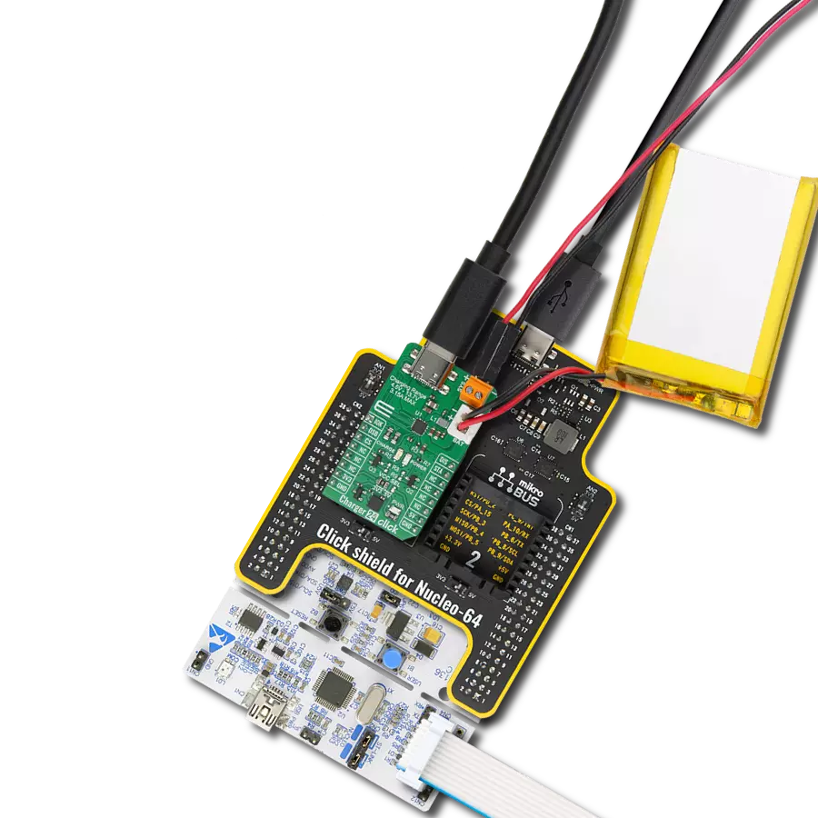
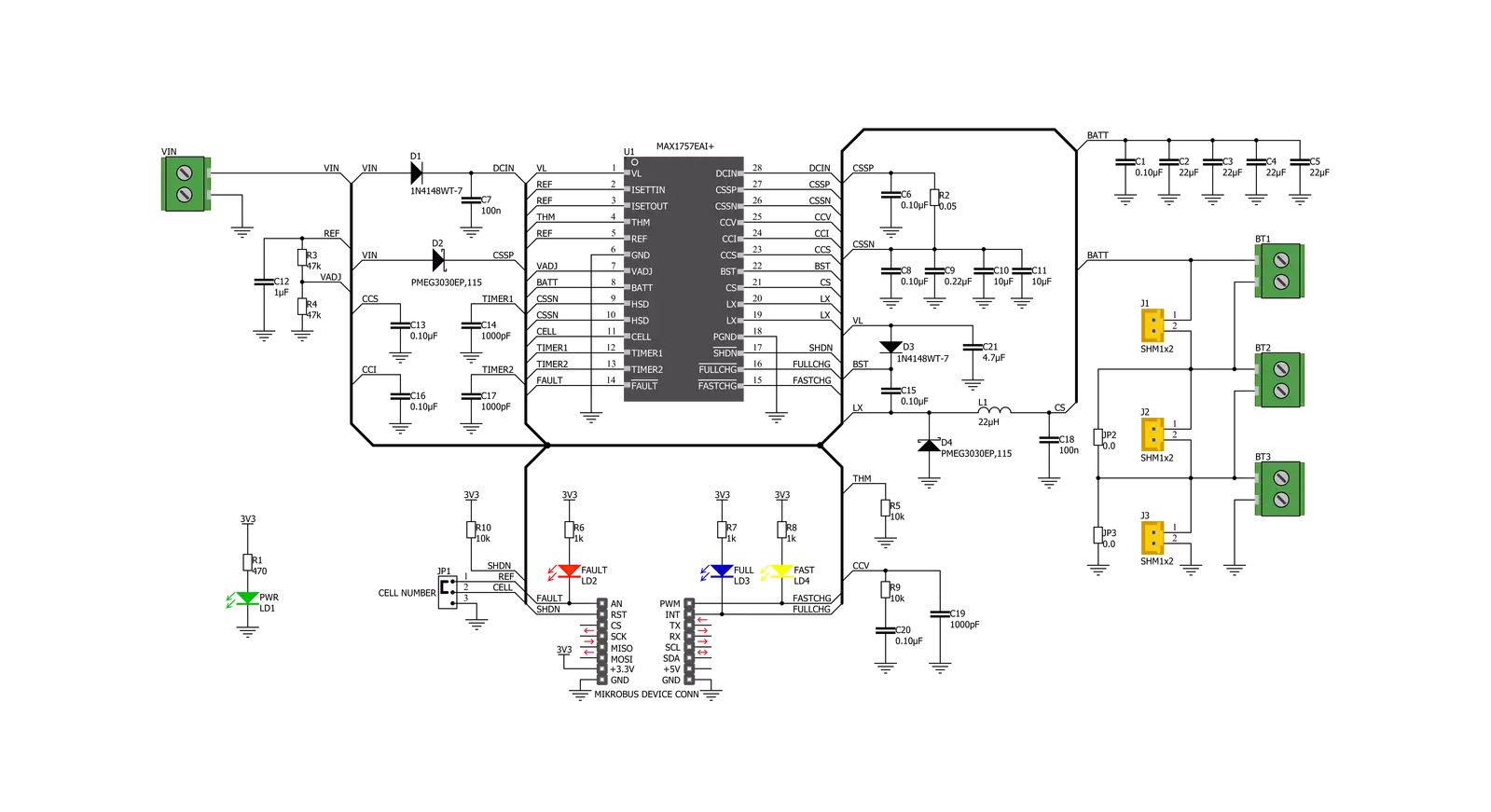
Charger 9 Click is based on the MAX1757, a stand-alone, switch-mode Li+ battery charger from Analog Devices. It can charge one to three lithium-ion (Li+, Li-Po) batteries with up to 1.5A. A set of onboard jumpers can select the number of batteries. The battery regulation voltage (VBATTR) is set to 4.2V per cell on this Click board™. The high accuracy of the integrated voltage limiter ensures reliable charging and prevents over-charging of the connected cell. The charging process is closely monitored and regulated by the extensive state machine with the addition of two timers, protecting the system if damaged battery cells are connected. Charger 9 Click requires an external power supply for its operation. To prevent an undervoltage lockout, the input voltage of the external power supply (VIN) should be at least 100mV larger than the voltage at the BT outputs (BAT pin of the MAX1757 IC). This prevents discharging of the batteries if the power source voltage drops too low. The maximum allowed voltage at the VIN terminal of the Charger 9 Click is 14V, while the input current limit is set to 2A. As mentioned, the MAX1757 uses an extensive state machine, which is explained in great detail in the datasheet. The state machine monitors the battery voltage (VBATT). After the IC reset, the MAX1757 (charger) enters the so-called
Prequalification mode. Based on the battery voltage level and the voltage of the input power supply (VIN > VBATT), the state machine decides to start the charging process. If the battery cell is deeply discharged, the charger tries to restore it by using 1/10 of the full charging current. Once the battery level is restored above the battery undervoltage level, and when all the other prerequisites are met, the charger starts the fast charging process by switching to the Constant Current (CC) mode (limited to 1.5A on this Click board™). This mode is indicated by a yellow LED indicator labeled as FAST and the LOW logic level at the CHG pin of the Click board™. When the battery charge level reaches 85% approx. (when the VBATT reaches the VBATTR, set to 4.2V on this Click board™) the charger switches to the Constant Voltage (CV) mode. This is indicated by a blue LED indicator labeled as FULL and the LOW logic level at the FUL pin of the Click board™. The charging current now starts to drop. When the battery charge reaches 95% approx. (charging current falls below 330mA) the charger enters the Top-Off mode, turning off all the LED indicators (CHG and FUL pins are at the HIGH logic level). The charger is still operated in the CV mode. After a timer expires, the charging process is done, and all the charging operations
are stopped until the battery voltage drops under the recharge voltage threshold (VBATT = 95% of the VBATTR). When this happens, the IC gets reset, and the state machine cycle is repeated. Each charging phase has a time-out period: if the time-out period is exceeded, an error will be indicated by a red LED labeled as FAULT and the LOW logic level at the FLT pin of the Click board™. An ongoing charging operation will be terminated to prevent any damage. The number of battery cells can be set by moving the SMD jumper labeled CELL NUMBER to an appropriate position (1 or 3). To select two cells, the SMD jumper should be unpopulated. The number of physically connected cell batteries must correspond to the number of cells set by the CELL NUMBER jumper. The CELL NUMBER jumper must be used with two additional SMD jumpers, JP2 and JP3. These two jumpers override unused connectors when the number of battery cells is less than 3. If a jumper does not override an unused connector, the GND path will be cut off from the connected battery (the battery cells are connected in series). By default, the number of battery cells is set to 3, so JP2 and JP3 should remain unpopulated. Charger 9 click offers XH-type connectors and 2-pole terminal screw connectors, allowing various types of Li+ batteries to connect.

Features overview
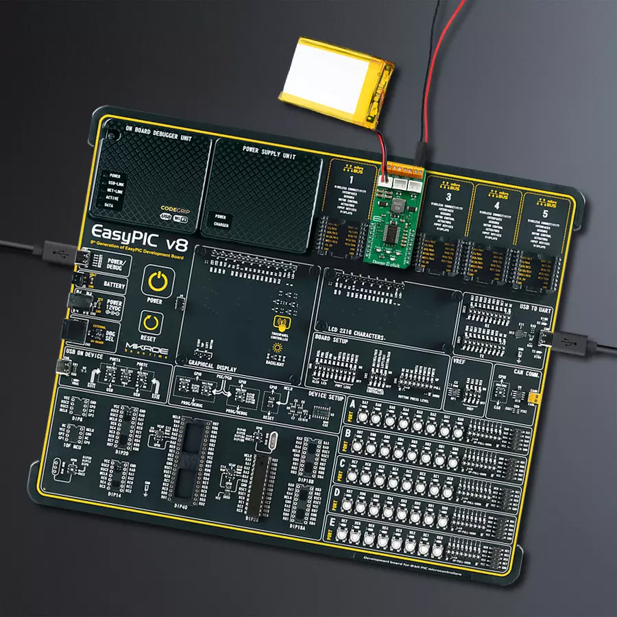
Development board
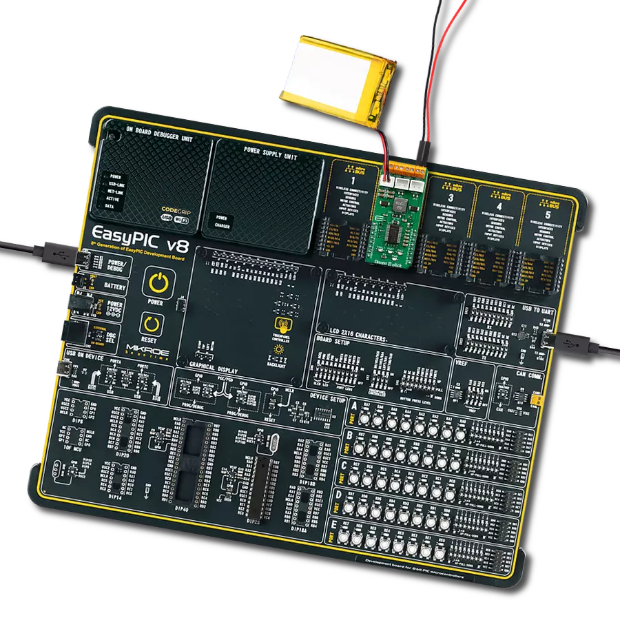
EasyPIC v8 is a development board specially designed for the needs of rapid development of embedded applications. It supports many high pin count 8-bit PIC microcontrollers from Microchip, regardless of their number of pins, and a broad set of unique functions, such as the first-ever embedded debugger/programmer. The development board is well organized and designed so that the end-user has all the necessary elements, such as switches, buttons, indicators, connectors, and others, in one place. Thanks to innovative manufacturing technology, EasyPIC v8 provides a fluid and immersive working experience, allowing access anywhere and under any
circumstances at any time. Each part of the EasyPIC v8 development board contains the components necessary for the most efficient operation of the same board. In addition to the advanced integrated CODEGRIP programmer/debugger module, which offers many valuable programming/debugging options and seamless integration with the Mikroe software environment, the board also includes a clean and regulated power supply module for the development board. It can use a wide range of external power sources, including a battery, an external 12V power supply, and a power source via the USB Type-C (USB-C) connector.
Communication options such as USB-UART, USB DEVICE, and CAN are also included, including the well-established mikroBUS™ standard, two display options (graphical and character-based LCD), and several different DIP sockets. These sockets cover a wide range of 8-bit PIC MCUs, from the smallest PIC MCU devices with only eight up to forty pins. EasyPIC v8 is an integral part of the Mikroe ecosystem for rapid development. Natively supported by Mikroe software tools, it covers many aspects of prototyping and development thanks to a considerable number of different Click boards™ (over a thousand boards), the number of which is growing every day.

Microcontroller Overview
MCU Card / MCU
Architecture
PIC
MCU Memory (KB)
64
Silicon Vendor
Microchip
Pin count
28
RAM (Bytes)
3648
You complete me!
Accessories
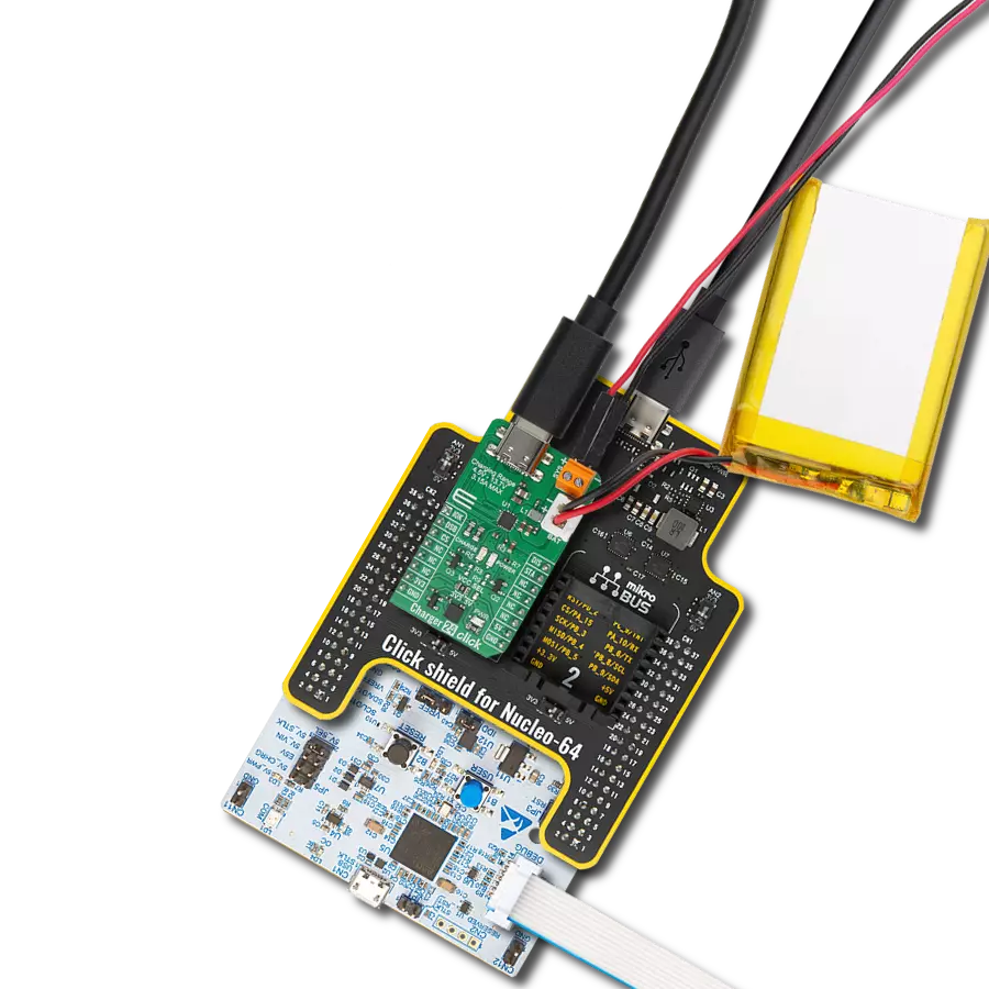
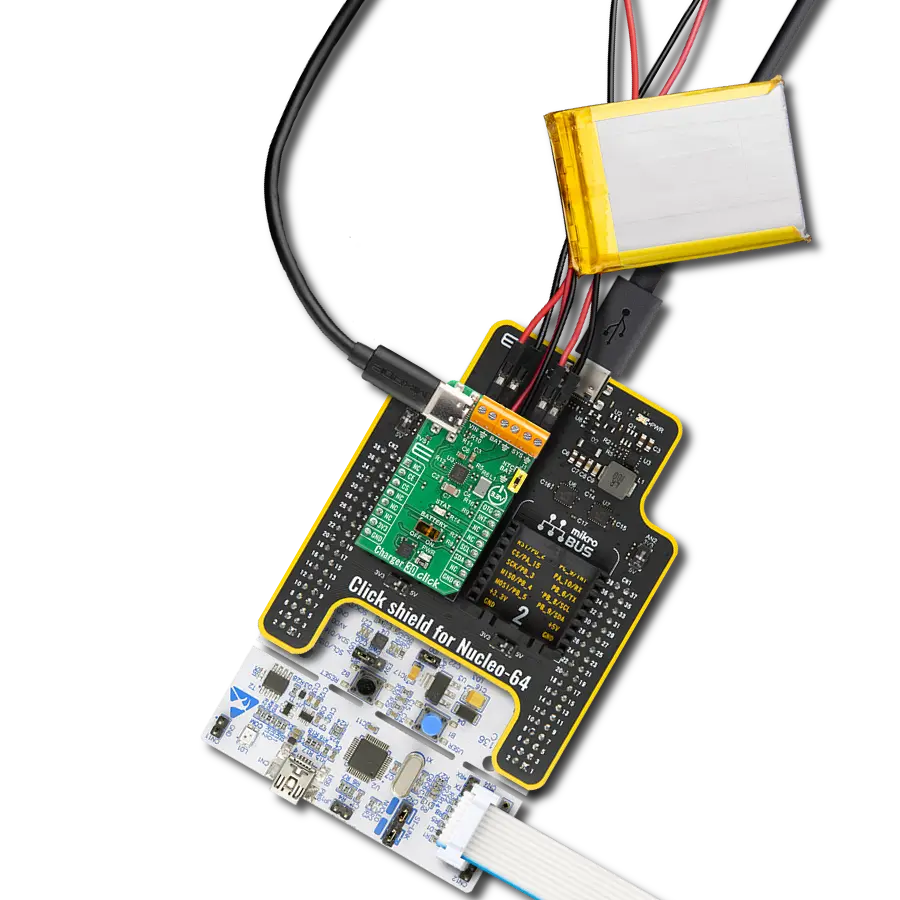
Li-Polymer Battery is the ideal solution for devices that demand a dependable and long-lasting power supply while emphasizing mobility. Its compatibility with mikromedia boards ensures easy integration without additional modifications. With a voltage output of 3.7V, the battery meets the standard requirements of many electronic devices. Additionally, boasting a capacity of 2000mAh, it can store a substantial amount of energy, providing sustained power for extended periods. This feature minimizes the need for frequent recharging or replacement. Overall, the Li-Polymer Battery is a reliable and autonomous power source, ideally suited for devices requiring a stable and enduring energy solution. You can find a more extensive choice of Li-Polymer batteries in our offer.

Used MCU Pins
mikroBUS™ mapper
Take a closer look
Click board™ Schematic
Step by step
Project assembly

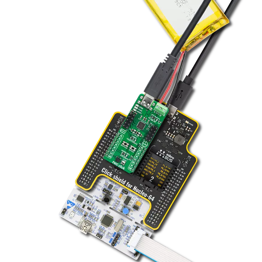
Start by selecting your development board and Click board™. Begin with the EasyPIC v8 as your development board.


Track your results in real time
Application Output
1. Application Output - In Debug mode, the 'Application Output' window enables real-time data monitoring, offering direct insight into execution results. Ensure proper data display by configuring the environment correctly using the provided tutorial.

2. UART Terminal - Use the UART Terminal to monitor data transmission via a USB to UART converter, allowing direct communication between the Click board™ and your development system. Configure the baud rate and other serial settings according to your project's requirements to ensure proper functionality. For step-by-step setup instructions, refer to the provided tutorial.

3. Plot Output - The Plot feature offers a powerful way to visualize real-time sensor data, enabling trend analysis, debugging, and comparison of multiple data points. To set it up correctly, follow the provided tutorial, which includes a step-by-step example of using the Plot feature to display Click board™ readings. To use the Plot feature in your code, use the function: plot(*insert_graph_name*, variable_name);. This is a general format, and it is up to the user to replace 'insert_graph_name' with the actual graph name and 'variable_name' with the parameter to be displayed.

Software Support
Library Description
This library contains API for Charger 9 Click driver.
Key functions:
charger9_enable- Enable functioncharger9_fast_charge_ind- Fast-Charge Indicate functioncharger9_full_charge_ind- Full-Charge Indicate function
Open Source
Code example
The complete application code and a ready-to-use project are available through the NECTO Studio Package Manager for direct installation in the NECTO Studio. The application code can also be found on the MIKROE GitHub account.
/*!
 * \file
 * \brief Charger 9 Click example
 *
 * # Description
 * This application is battery charger, capable of charging one, two or three battery cells.
 *
 * The demo application is composed of two sections :
 *
 * ## Application Init
 * Initializes GPIO driver and turns OFF the charger as initial state.
 *
 * ## Application Task
 * Checks which command was sent by user and performs the selected command.
 * Also checks the fault condition, and when fault condition is detected sends a report message to the uart terminal
 * and turns OFF the charger.
 *
 * *note:*
 * When user sends a desired command to the charger, a report message will be sent to the uart terminal as
 * indication to the user.
 * The possible commands, for Charger 9 control, will be written to the uart terminal.
 * The alarm sound will be generated on the determined commands: enable, disable and fault condition detecting.
 *
 * \author MikroE Team
 *
 */
// ------------------------------------------------------------------- INCLUDES

#include "board.h"
#include "log.h"
#include "charger9.h"

// ------------------------------------------------------------------ VARIABLES

static charger9_t charger9;
static log_t logger;
static CHARGER9_STATE en_flag;

// ------------------------------------------------------ APPLICATION FUNCTIONS

void application_init ( void )
{
    log_cfg_t log_cfg;
    charger9_cfg_t cfg;

    /**
     * Logger initialization.
     * Default baud rate: 115200
     * Default log level: LOG_LEVEL_DEBUG
     * @note If USB_UART_RX and USB_UART_TX
     * are defined as HAL_PIN_NC, you will
     * need to define them manually for log to work.
     * See @b LOG_MAP_USB_UART macro definition for detailed explanation.
     */
    LOG_MAP_USB_UART( log_cfg );
    log_init( &logger, &log_cfg );
    log_info( &logger, "---- Application Init ----" );

    //  Click initialization.

    charger9_cfg_setup( &cfg );
    CHARGER9_MAP_MIKROBUS( cfg, MIKROBUS_1 );
    charger9_init( &charger9, &cfg );

    charger9_enable( &charger9, CHARGER9_DISABLE );
    en_flag = CHARGER9_DISABLE;
    Delay_ms ( 100 );

    log_printf( &logger, "** Charger 9 initialization done ** \r\n" );
}

void application_task ( )
{
    CHARGER9_RETVAL charge_state;

    if ( en_flag == CHARGER9_DISABLE )
    {
        charger9_enable( &charger9, CHARGER9_ENABLE );
        en_flag = CHARGER9_ENABLE;

        Delay_ms ( 1000 );
        Delay_ms ( 1000 );
        log_printf( &logger, "** Charger 9 is enabled ** \r\n" );
    }

    charge_state = charger9_full_charge_ind( &charger9 );

    if ( charge_state == CHARGER9_IND_ACTIVE )
    {
        log_printf( &logger, "** Full-Charge state ** \r\n" );
        Delay_ms ( 1000 );
        Delay_ms ( 1000 );
    }

    charge_state = charger9_fast_charge_ind( &charger9 );
    if ( charge_state == CHARGER9_IND_ACTIVE )
    {
        log_printf( &logger, "** Fast-Charge state ** \r\n" );
        Delay_ms ( 1000 );
        Delay_ms ( 1000 );
    }

    charge_state = charger9_fault_ind ( &charger9 );

    if ( charge_state == CHARGER9_IND_ACTIVE )
    {
        charger9_enable( &charger9, CHARGER9_DISABLE );
        en_flag = CHARGER9_DISABLE;

        Delay_ms ( 1000 );
        Delay_ms ( 1000 );
        Delay_ms ( 1000 );
        log_printf( &logger, "** Fault condition! ** \r\n" );
        log_printf( &logger, "** Charger 9 is disabled ** \r\n" );
    }
}

int main ( void )
{
    /* Do not remove this line or clock might not be set correctly. */
    #ifdef PREINIT_SUPPORTED
    preinit();
    #endif

    application_init( );

    for ( ; ; )
    {
        application_task( );
    }

    return 0;
}

// ------------------------------------------------------------------------ END