Verify and authenticate individuals with their unique fingerprint patterns using A-172-MRQ and PIC18LF25K80
Beyond passwords

Published Nov 01, 2023
Click board™
Fingerprint 2 Click
Dev. board
EasyPIC v8
Compiler
NECTO Studio
MCU
PIC18LF25K80
Implement biometric fingerprint recognition and enable accurate and unique identification of individuals for secure access to digital systems and physical spaces
A
A
Hardware Overview
How does it work?
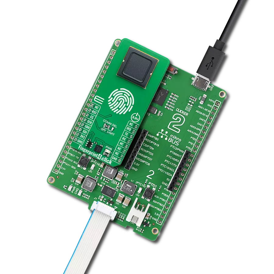
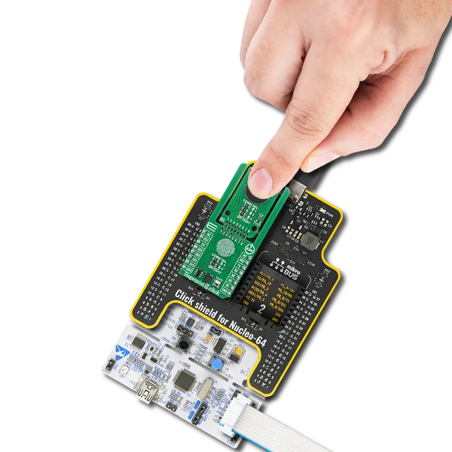
Fingerprint 2 Click is based on the A-172-MRQ, a 2D capacitive fingerprint sensor from ByNew Technology with an active scanning area of 8.8 x 8x8 mm and a 176 x 176 pixels resolution. The sensor is based on capacitive-contact technology with a hardened surface and enhanced ESD immunity. On board, Nuvoton M2301 MCU, which serves as interface IC and control unit, interfaces this sensor over a high-speed SPI interface and comes with built-in fingerprint matching capability while leaving most of the chip resource to application developers. Developers can develop fingerprint-related products based on the
communication protocol without advanced knowledge of fingerprint identification. The Fingerprint 2 Click has stable performance and a simple structure. The simplified functions for faster and easy development include fingerprint comparison, image scanning transmission, search, registered fingerprint storage, and the system's unique internal code protection mechanism. The fingerprint comparison program can register at most 24 fingerprints, the comparison speed is fast, and the correct rate is very high. Thanks to the Nuvoton MCU with the on-chip crypto-accelerator, Cortex-M23 TrustZone, and XOM facilities that
communicate with the fingerprint sensor and provide information to the host, the Fingerprint 2 Click board can be interfaced with commands over UART protocol (baud rate 115200) or USB 2.0 full speed. Fingerprint 2 Click needs to be supplied with 3.3V and 5V for proper operation. However, note that this board is designed to be operated only with 3.3V logic levels. Therefore a proper logic voltage level conversion should be performed before the Click board™ is used with MCUs with logic levels of 5V.

Features overview
Development board
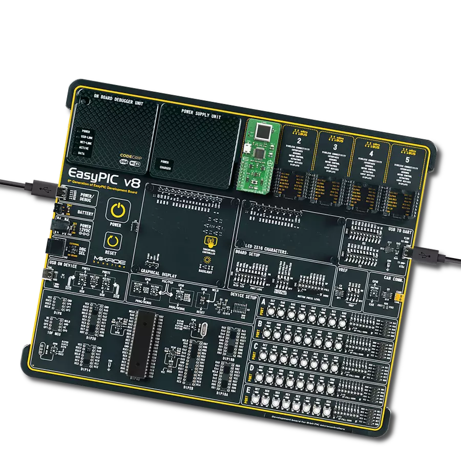
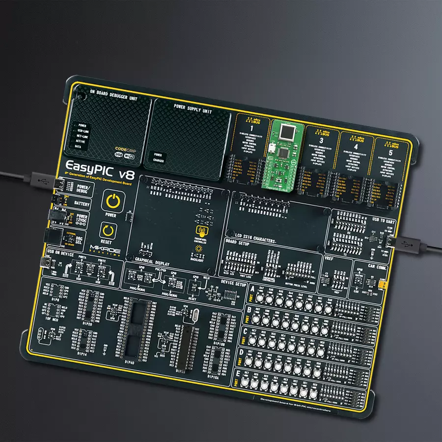
EasyPIC v8 is a development board specially designed for the needs of rapid development of embedded applications. It supports many high pin count 8-bit PIC microcontrollers from Microchip, regardless of their number of pins, and a broad set of unique functions, such as the first-ever embedded debugger/programmer. The development board is well organized and designed so that the end-user has all the necessary elements, such as switches, buttons, indicators, connectors, and others, in one place. Thanks to innovative manufacturing technology, EasyPIC v8 provides a fluid and immersive working experience, allowing access anywhere and under any
circumstances at any time. Each part of the EasyPIC v8 development board contains the components necessary for the most efficient operation of the same board. In addition to the advanced integrated CODEGRIP programmer/debugger module, which offers many valuable programming/debugging options and seamless integration with the Mikroe software environment, the board also includes a clean and regulated power supply module for the development board. It can use a wide range of external power sources, including a battery, an external 12V power supply, and a power source via the USB Type-C (USB-C) connector.
Communication options such as USB-UART, USB DEVICE, and CAN are also included, including the well-established mikroBUS™ standard, two display options (graphical and character-based LCD), and several different DIP sockets. These sockets cover a wide range of 8-bit PIC MCUs, from the smallest PIC MCU devices with only eight up to forty pins. EasyPIC v8 is an integral part of the Mikroe ecosystem for rapid development. Natively supported by Mikroe software tools, it covers many aspects of prototyping and development thanks to a considerable number of different Click boards™ (over a thousand boards), the number of which is growing every day.

Microcontroller Overview
MCU Card / MCU

Architecture
PIC
MCU Memory (KB)
32
Silicon Vendor
Microchip
Pin count
28
RAM (Bytes)
3648
Used MCU Pins
mikroBUS™ mapper
Take a closer look
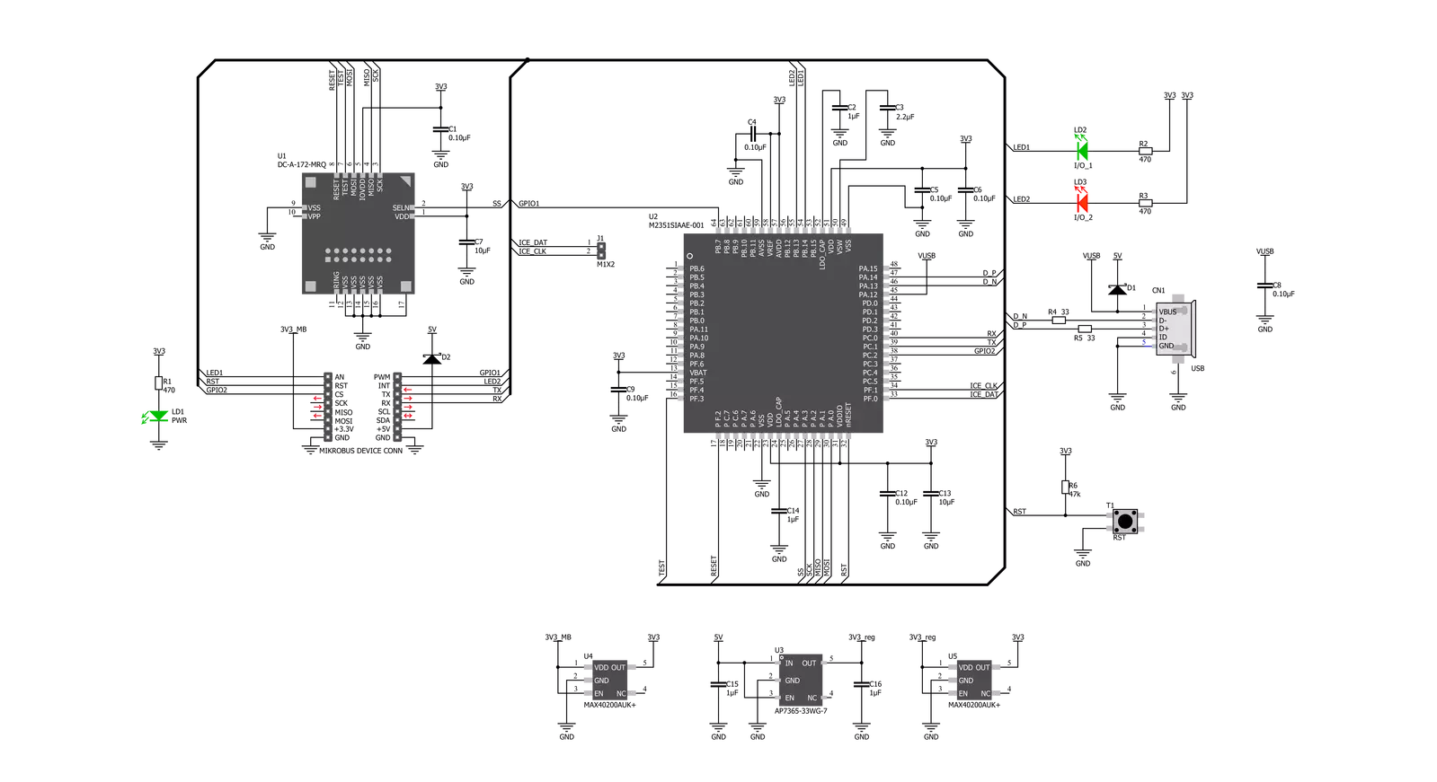
Click board™ Schematic
Step by step
Project assembly

Start by selecting your development board and Click board™. Begin with the EasyPIC v8 as your development board.


Software Support
Library Description
This library contains API for Fingerprint 2 Click driver.
Key functions:
fingerprint2_reg_one_fp- This function registrates fingerprint on indexfingerprint2_delete_one_fp- This function deletes fingerprint on indexfingerprint2_reset- This function restarts device
Open Source
Code example
The complete application code and a ready-to-use project are available through the NECTO Studio Package Manager for direct installation in the NECTO Studio. The application code can also be found on the MIKROE GitHub account.
/*!
 * \file
 * \brief Fingerprint2 Click example
 *
 * # Description
 * This example demonstrates the use of Fingerprint 2 Click board.
 *
 * The demo application is composed of two sections :
 *
 * ## Application Init
 * Initializes the driver, enables the Click board, and then executes a command for
 * registering a fingerprint.
 *
 * ## Application Task
 * Compares a fingerprint on input to the registered fingerprint and
 * displays the results on the USB UART every 5 seconds.
 *
 * ## Additional Functions
 * - fingerprint2_process ( ) - The general process of collecting data the module sends.
 * - fp_reg_one ( uint8_t fngr_number ) - Registers a fingerprint at a specific index number.
 * - fp_clr_one ( uint8_t fngr_number ) - Deletes a fingerprint from a specific index number.
 * - fp_clr_all ( ) - Clears all fingerprints.
 * - fp_curr_state (  ) - Lists the registration status and returns the number of registered fingerprints.
 * - fp_compare ( ) - Compares a fingerprint on input to all other fingerprints that are memorized.
 *
 * @note
 * In the registration state each fingerprint needs to be enrolled 3 times.
 *
 * \author MikroE Team
 *
 */
// ------------------------------------------------------------------- INCLUDES

#include "board.h"
#include "log.h"
#include "fingerprint2.h"
#include "string.h"

#define PROCESS_COUNTER 100
#define PROCESS_RX_BUFFER_SIZE 800

// ------------------------------------------------------------------ VARIABLES

static fingerprint2_t fingerprint2;
static log_t logger;

uint8_t flag;

// ------------------------------------------------------- ADDITIONAL FUNCTIONS

static void fingerprint2_process ( void )
{
    int32_t rsp_size;

    uint8_t check_buf_cnt;
    uint8_t process_cnt = PROCESS_COUNTER;
    char uart_rx_buffer[ PROCESS_RX_BUFFER_SIZE ] = { 0 };
    flag = 0;

    while( process_cnt != 0 )
    {
        rsp_size = fingerprint2_generic_read( &fingerprint2, &uart_rx_buffer, PROCESS_RX_BUFFER_SIZE );

        if ( rsp_size > 0 )
        {
            // Validation of the received data
            for ( check_buf_cnt = 0; check_buf_cnt < rsp_size; check_buf_cnt++ )
            {
                if ( uart_rx_buffer[ check_buf_cnt ] == 0 )
                {
                    uart_rx_buffer[ check_buf_cnt ] = 13;
                }
            }

            log_printf( &logger, "%s", uart_rx_buffer );

            if ( strstr( uart_rx_buffer, "</R>" ) )
            {
                flag = 1;
                process_cnt = 5;
            }

            // Clear RX buffer
            memset( uart_rx_buffer, 0, PROCESS_RX_BUFFER_SIZE );
        }
        else
        {
            process_cnt--;

            // Process delay
            Delay_100ms( );
        }
    }
}

//Write index number of fingeprint to be store: from 0 to 23
void fp_reg_one ( uint8_t fngr_number )
{
    log_printf( &logger, "Registration process\r\n" );
    Delay_ms ( 500 );

    fingerprint2_reg_one_fp( &fingerprint2, fngr_number );
    do
    {
        fingerprint2_process(  );
    }
    while ( flag == 0 );
}

// Write index number of fingeprint to be deleted: from 0 to 23
void fp_clr_one ( uint8_t fngr_number )
{
    log_printf( &logger, "Deleting process\r\n" );
    Delay_ms ( 500 );

    fingerprint2_delete_one_fp( &fingerprint2, fngr_number );
    do
    {
        fingerprint2_process(  );
    }
    while ( flag == 0 );
}

// Delete all fingeprints: from 0 to 23
void fp_clr_all ( )
{
    uint8_t cnt = 0;
    log_printf( &logger, "Process of deleting all fingeprints\r\n" );
    Delay_ms ( 500 );

    while ( cnt < 23 )
    {
        fingerprint2_delete_one_fp( &fingerprint2, cnt );
        cnt++;
        do
        {
            fingerprint2_process(  );
        }
        while ( flag == 0 );
    }
}

// Current state ( number of memorized fingerprints )
void fp_curr_state ( )
{
    fingerprint2_generic_write( &fingerprint2, FINGERPRINT2_CMD_FP_REG_NO, strlen( FINGERPRINT2_CMD_FP_REG_NO ) );
    do
    {
        fingerprint2_process(  );
    }
    while ( flag == 0 );
}

// Compare fingerprint on input with all other fingerprints that are memorized.
void fp_compare ( )
{
    fingerprint2_generic_write( &fingerprint2, FINGERPRINT2_CMD_FP_CMP, strlen( FINGERPRINT2_CMD_FP_CMP ) );
    fingerprint2_process(  );

    do
    {
        fingerprint2_process(  );
    }
    while ( flag == 0 );
}

// ------------------------------------------------------ APPLICATION FUNCTIONS

void application_init ( void )
{
    log_cfg_t log_cfg;
    fingerprint2_cfg_t cfg;

    /**
     * Logger initialization.
     * Default baud rate: 115200
     * Default log level: LOG_LEVEL_DEBUG
     * @note If USB_UART_RX and USB_UART_TX
     * are defined as HAL_PIN_NC, you will
     * need to define them manually for log to work.
     * See @b LOG_MAP_USB_UART macro definition for detailed explanation.
     */
    LOG_MAP_USB_UART( log_cfg );
    log_init( &logger, &log_cfg );
    log_info( &logger, "---- Application Init ----" );

    //  Click initialization.

    fingerprint2_cfg_setup( &cfg );
    FINGERPRINT2_MAP_MIKROBUS( cfg, MIKROBUS_1 );
    fingerprint2_init( &fingerprint2, &cfg );

    fingerprint2_reset ( &fingerprint2 );
    Delay_ms ( 1000 );

    fp_reg_one( 0 );
    Delay_ms ( 1000 );
}

void application_task ( void )
{
    fp_compare( );
    Delay_ms ( 1000 );
    Delay_ms ( 1000 );
    Delay_ms ( 1000 );
    Delay_ms ( 1000 );
    Delay_ms ( 1000 );
}

int main ( void )
{
    /* Do not remove this line or clock might not be set correctly. */
    #ifdef PREINIT_SUPPORTED
    preinit();
    #endif

    application_init( );

    for ( ; ; )
    {
        application_task( );
    }

    return 0;
}


// ------------------------------------------------------------------------ END