Accurately quantify applied forces with FSR and PIC18F2585 for enhanced analysis
Unveiling force measurement like never before!

Published Nov 01, 2023
Click board™
Force Click
Dev. board
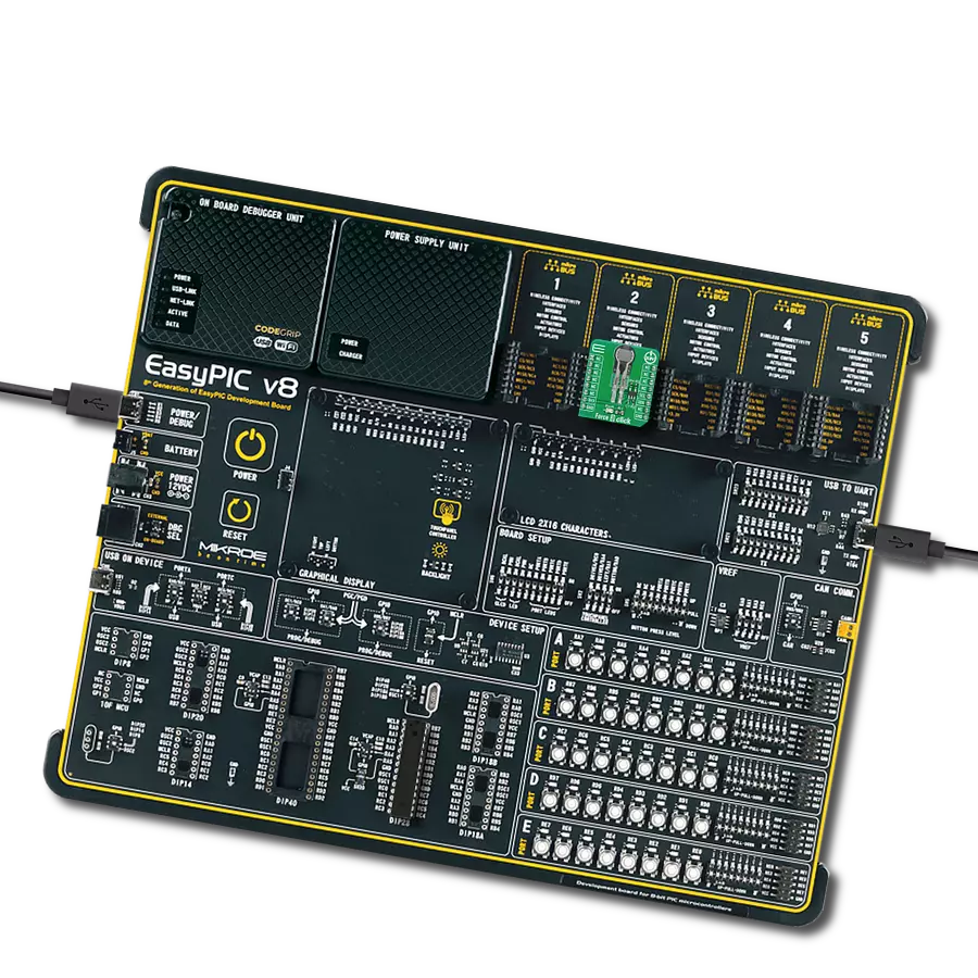
EasyPIC v8
Compiler
NECTO Studio
MCU
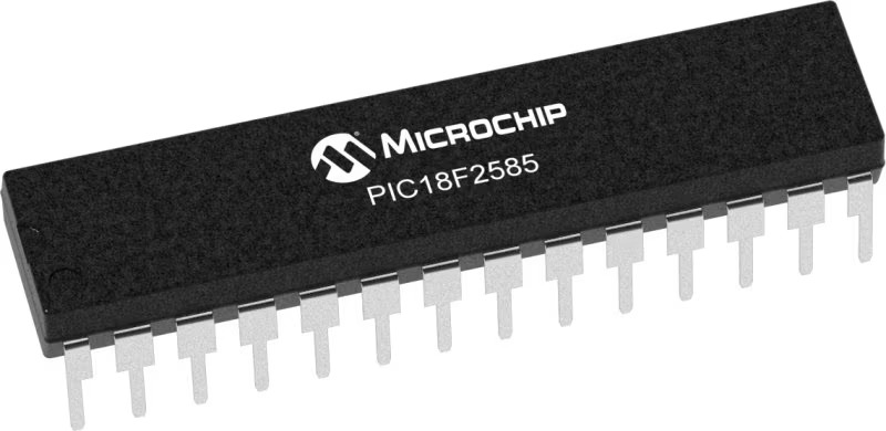
PIC18F2585
Harness the power of precise force measurement to enhance quality control across various applications
A
A
Hardware Overview
How does it work?
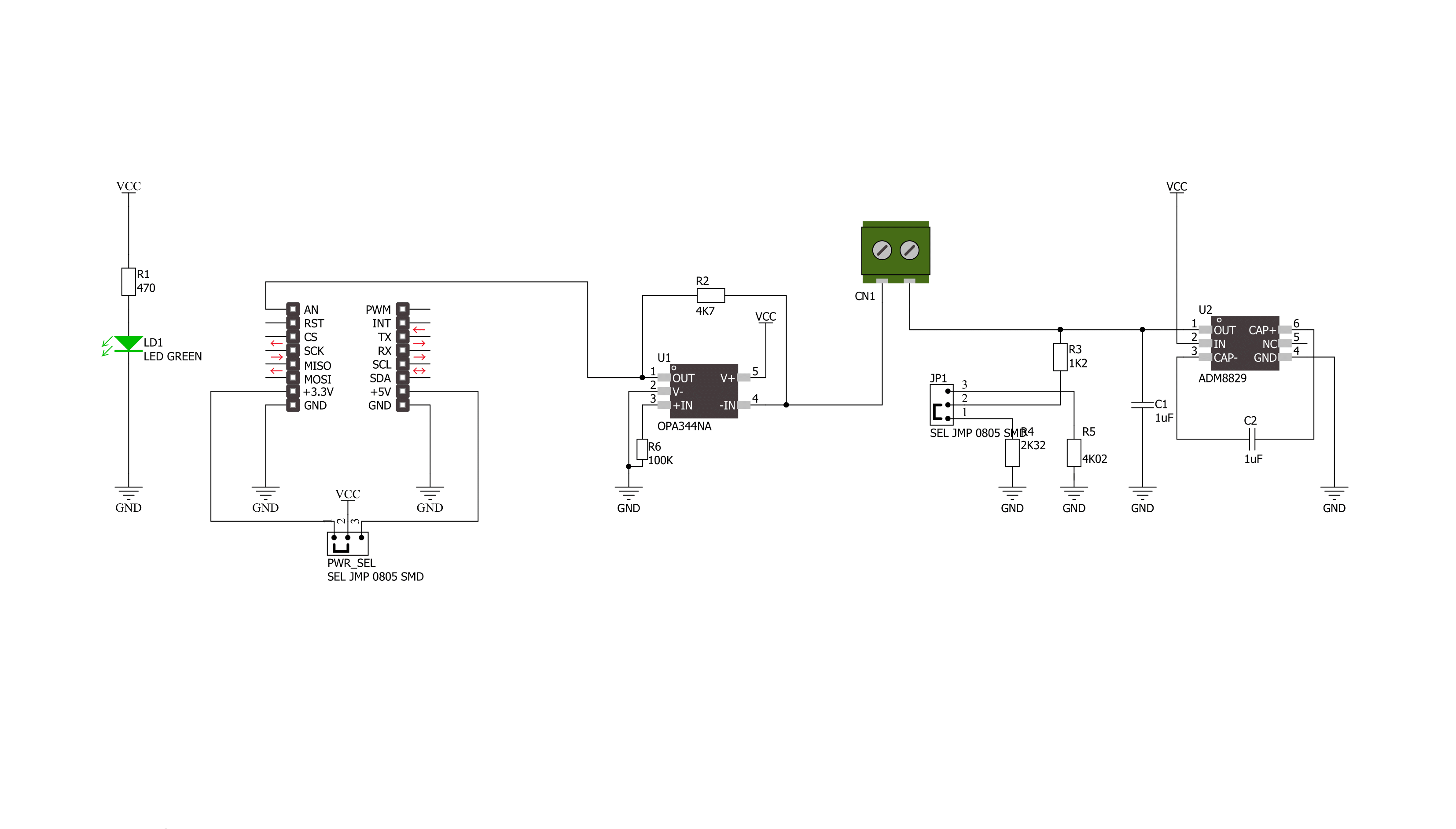
Force Click is based on the circuitry that allows the implementation of Force Sensing Resistors from Interlink Electronics. The Force Sensing Resistor is a thin sensor made of two membranes separated by a spacer around the edges. When pressed, the gap between the two membranes gets closed. This shorts the two membranes together with a resistance proportional to the applied force. This force sensitivity is optimized for human-machine interface devices, including automotive electronics, medical systems, industrial controls, and robotics. The FSR is a robust sensor with up to 10M of actuation and features a low device rise time of under 3 microseconds, as well as continuous analog force resolution. Force Click
sends analog values to the host MCU over the AN pin of the mikroBUS™ socket by using an OPA344, a low-power, single supply, rail-to-rail operational amplifier from Texas Instruments. This unity-gain stable OPAMP is ideal for driving sampling analog to digital converters. Rail-to-rail input and output swing significantly increase dynamic range, especially in low-power supply applications. The input to this OPA344NA is driven directly from the screw terminal and the force-sensing resistor. An ADM8829, a switched-capacitor voltage inverter with shutdown from Analog Devices, feeds the other side of the screw terminal and the force-sensing resistor. This charge-pump voltage inverter generates a negative power supply
from a positive input. The voltage conversion task is achieved using a switched capacitor technique using two external charge storage capacitors. An on-chip oscillator and switching network transfers charge between the charge storage capacitors. This Click board™ can operate with either 3.3V or 5V logic voltage levels selected via the PWR SEL jumper. This way, both 3.3V and 5V capable MCUs can use the communication lines properly. Also, this Click board™ comes equipped with a library containing easy-to-use functions and an example code that can be used as a reference for further development.


Features overview
Development board
EasyPIC v8 is a development board specially designed for the needs of rapid development of embedded applications. It supports many high pin count 8-bit PIC microcontrollers from Microchip, regardless of their number of pins, and a broad set of unique functions, such as the first-ever embedded debugger/programmer. The development board is well organized and designed so that the end-user has all the necessary elements, such as switches, buttons, indicators, connectors, and others, in one place. Thanks to innovative manufacturing technology, EasyPIC v8 provides a fluid and immersive working experience, allowing access anywhere and under any
circumstances at any time. Each part of the EasyPIC v8 development board contains the components necessary for the most efficient operation of the same board. In addition to the advanced integrated CODEGRIP programmer/debugger module, which offers many valuable programming/debugging options and seamless integration with the Mikroe software environment, the board also includes a clean and regulated power supply module for the development board. It can use a wide range of external power sources, including a battery, an external 12V power supply, and a power source via the USB Type-C (USB-C) connector.
Communication options such as USB-UART, USB DEVICE, and CAN are also included, including the well-established mikroBUS™ standard, two display options (graphical and character-based LCD), and several different DIP sockets. These sockets cover a wide range of 8-bit PIC MCUs, from the smallest PIC MCU devices with only eight up to forty pins. EasyPIC v8 is an integral part of the Mikroe ecosystem for rapid development. Natively supported by Mikroe software tools, it covers many aspects of prototyping and development thanks to a considerable number of different Click boards™ (over a thousand boards), the number of which is growing every day.

Microcontroller Overview
MCU Card / MCU
Architecture
PIC
MCU Memory (KB)
48
Silicon Vendor
Microchip
Pin count
28
RAM (Bytes)
3328
Used MCU Pins
mikroBUS™ mapper
Take a closer look
Click board™ Schematic
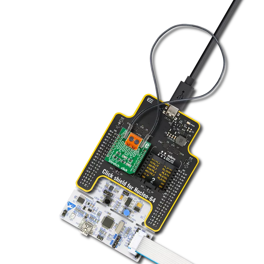
Step by step
Project assembly

Start by selecting your development board and Click board™. Begin with the EasyPIC v8 as your development board.


Software Support
Library Description
This library contains API for Force Click driver.
Key functions:
force_generic_read- This function reads ADC dataforce_get_resistance- This function calculates resistance data based on the ADC inputforce_get_correction_factor- This function calculates the correction factor based on temperature and humidity data
Open Source
Code example
The complete application code and a ready-to-use project are available through the NECTO Studio Package Manager for direct installation in the NECTO Studio. The application code can also be found on the MIKROE GitHub account.
/*!
 * \file
 * \brief Force Click example
 *
 * # Description
 * This example showcases how to initialize and configure the logger and Click modules and
 * read and display ADC voltage data read from the analog pin.
 *
 * The demo application is composed of two sections :
 *
 * ## Application Init
 * This function initializes and configures the logger and Click modules.
 *
 * ## Application Task
 * This function reads and displays ADC voltage data from the analog pin every second.
 *
 * \author MikroE Team
 *
 */
// ------------------------------------------------------------------- INCLUDES

#include "board.h"
#include "log.h"
#include "force.h"

// ------------------------------------------------------------------ VARIABLES

static force_t force;
static log_t logger;

// ------------------------------------------------------ APPLICATION FUNCTIONS

void application_init ( )
{
    log_cfg_t log_cfg;
    force_cfg_t cfg;

    /**
     * Logger initialization.
     * Default baud rate: 115200
     * Default log level: LOG_LEVEL_DEBUG
     * @note If USB_UART_RX and USB_UART_TX
     * are defined as HAL_PIN_NC, you will
     * need to define them manually for log to work.
     * See @b LOG_MAP_USB_UART macro definition for detailed explanation.
     */
    LOG_MAP_USB_UART( log_cfg );
    log_init( &logger, &log_cfg );
    log_info( &logger, "---- Application Init ----" );

    log_printf( &logger, "--------------------\r\n" );
    log_printf( &logger, "    Force  Click    \r\n" );
    log_printf( &logger, "--------------------\r\n\r\n" );

    //  Click initialization.

    force_cfg_setup( &cfg );
    FORCE_MAP_MIKROBUS( cfg, MIKROBUS_1 );
    force_init( &force, &cfg );
}

void application_task ( )
{
    force_data_t tmp;

    //  Task implementation.

    tmp = force_generic_read ( &force );
    log_printf( &logger, " * ADC value : %d \r\n", tmp );
    log_printf( &logger, "--------------------- \r\n" );
    Delay_ms ( 1000 );
}

int main ( void )
{
    /* Do not remove this line or clock might not be set correctly. */
    #ifdef PREINIT_SUPPORTED
    preinit();
    #endif

    application_init( );

    for ( ; ; )
    {
        application_task( );
    }

    return 0;
}

// ------------------------------------------------------------------------ END