Expand the number of input/output (I/O) pins in your system with TCAL9538 and PIC18LF26K40
8-bit I2C-bus I/O expander in a Click Snap form factor
Published Sep 24, 2024
Click board™
Expand 19 Click
Dev. board
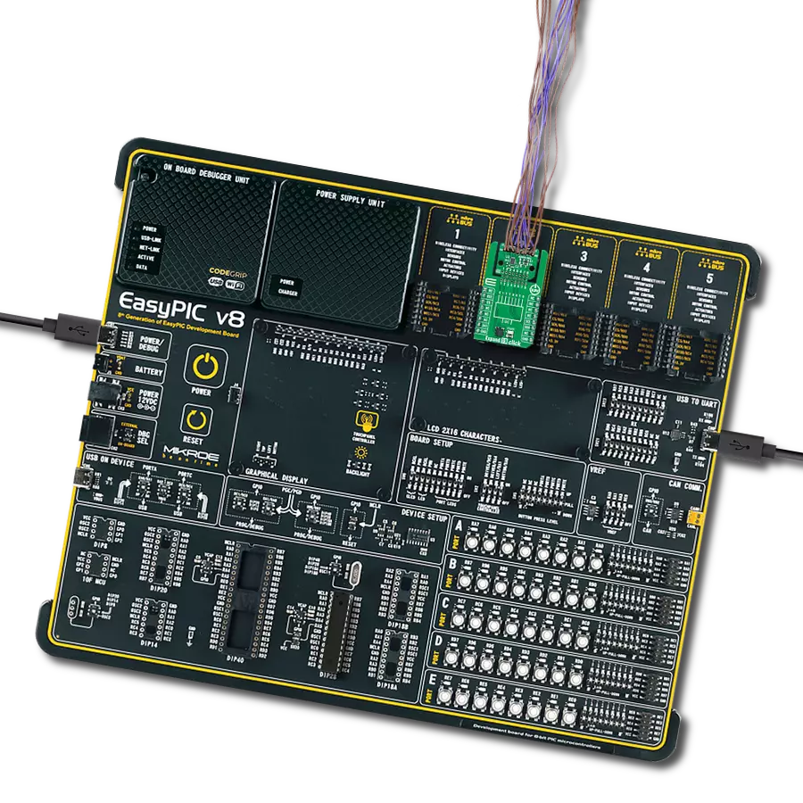
EasyPIC v8
Compiler
NECTO Studio
MCU
PIC18LF26K40
Add additional general I/O pins for a variety of applications
A
A
Hardware Overview
How does it work?
Expand 19 Click is based on the TCAL9538, an 8-bit I2C-bus I/O expander from Texas Instruments. This Click board™ provides a simple solution for applications that require additional input/output lines, such as controlling switches, sensors, push-buttons, LEDs, and more. Operating at 3.3V, the TCAL9538 allows easy integration into existing systems using the standard two-wire I2C communication protocol. At its core, the TCAL9538 features 8-bit data registers that enable users to configure the I/O pins as inputs or outputs. Upon power-up or a software reset, all I/Os are set as inputs by default. However, they can be reconfigured by the host microcontroller through the Configuration registers. The data for each pin is stored in dedicated Input Port or Output Port registers, which are accessible for reading by the host MCU. Additionally, the polarity of the Input Port can be adjusted via the Polarity Inversion register, offering flexibility in design and signal interpretation. This Click board™ is designed in a
unique format supporting the newly introduced MIKROE feature called "Click Snap." Unlike the standardized version of Click boards, this feature allows the main sensor area to become movable by breaking the PCB, opening up many new possibilities for implementation. Thanks to the Snap feature, the TCAL9538 can operate autonomously by accessing its signals directly on the pins marked 1-8. Additionally, the Snap part includes a specified and fixed screw hole position, enabling users to secure the Snap board in their desired location. One of the key features of the TCAL9538 is its Agile I/O functionality, which enhances the performance of the I/O ports. This includes configurable output drive strength, programmable pull-up and pull-down resistors, latchable inputs, and maskable interrupts. The device also offers programmable open-drain or push-pull output modes, making it adaptable to various application requirements. These Agile I/O features provide the flexibility to optimize your design for power
consumption, speed, and electromagnetic interference (EMI). Expand 19 Click uses an I2C interface with clock speeds of up to 1MHz, ensuring fast and efficient communication with the host MCU. The I2C address can be easily configured via onboard jumpers, allowing multiple devices tocoexist on the same bus. Additionally, the board features an interrupt (INT) pin triggered whenever there is a change in the state of any input port, ensuring real-time response to external events, and a reset (RST) pin for power cycling to return the device to its default state. This ensures reliable operation and easy recovery in case of unexpected issues. This Click board™ can be operated only with a 3.3V logic voltage level. The board must perform appropriate logic voltage level conversion before using MCUs with different logic levels. Also, it comes equipped with a library containing functions and an example code that can be used as a reference for further development.

Features overview
Development board
EasyPIC v8 is a development board specially designed for the needs of rapid development of embedded applications. It supports many high pin count 8-bit PIC microcontrollers from Microchip, regardless of their number of pins, and a broad set of unique functions, such as the first-ever embedded debugger/programmer. The development board is well organized and designed so that the end-user has all the necessary elements, such as switches, buttons, indicators, connectors, and others, in one place. Thanks to innovative manufacturing technology, EasyPIC v8 provides a fluid and immersive working experience, allowing access anywhere and under any
circumstances at any time. Each part of the EasyPIC v8 development board contains the components necessary for the most efficient operation of the same board. In addition to the advanced integrated CODEGRIP programmer/debugger module, which offers many valuable programming/debugging options and seamless integration with the Mikroe software environment, the board also includes a clean and regulated power supply module for the development board. It can use a wide range of external power sources, including a battery, an external 12V power supply, and a power source via the USB Type-C (USB-C) connector.
Communication options such as USB-UART, USB DEVICE, and CAN are also included, including the well-established mikroBUS™ standard, two display options (graphical and character-based LCD), and several different DIP sockets. These sockets cover a wide range of 8-bit PIC MCUs, from the smallest PIC MCU devices with only eight up to forty pins. EasyPIC v8 is an integral part of the Mikroe ecosystem for rapid development. Natively supported by Mikroe software tools, it covers many aspects of prototyping and development thanks to a considerable number of different Click boards™ (over a thousand boards), the number of which is growing every day.

Microcontroller Overview
MCU Card / MCU
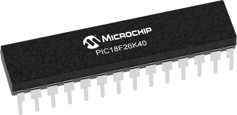
Architecture
PIC
MCU Memory (KB)
64
Silicon Vendor
Microchip
Pin count
28
RAM (Bytes)
3728
Used MCU Pins
mikroBUS™ mapper
Take a closer look
Click board™ Schematic

Step by step
Project assembly

Start by selecting your development board and Click board™. Begin with the EasyPIC v8 as your development board.


Software Support
Library Description
This library contains API for Expand 19 Click driver.
Key functions:
expand19_set_pin_direction- This function sets the direction of the selected pins.expand19_set_all_pins_value- This function sets the value of all output pins.expand19_read_port_value- This function reads the value of all input pins.
Open Source
Code example
The complete application code and a ready-to-use project are available through the NECTO Studio Package Manager for direct installation in the NECTO Studio. The application code can also be found on the MIKROE GitHub account.
/*!
 * @file main.c
 * @brief Expand 19 Click example
 *
 * # Description
 * This example demonstrates the use of Expand 19 Click board by setting and
 * reading the port state.
 *
 * The demo application is composed of two sections :
 *
 * ## Application Init
 * Initializes the driver and performs the Click default configuration which sets
 * the pins 0-3 as output and others as input with pull-up enabled.
 *
 * ## Application Task
 * Sets the output pins and then reads the status of all pins and
 * displays the results on the USB UART approximately once per second.
 *
 * @author Stefan Filipovic
 *
 */

#include "board.h"
#include "log.h"
#include "expand19.h"

static expand19_t expand19;
static log_t logger;

void application_init ( void )
{
    log_cfg_t log_cfg;  /**< Logger config object. */
    expand19_cfg_t expand19_cfg;  /**< Click config object. */

    /**
     * Logger initialization.
     * Default baud rate: 115200
     * Default log level: LOG_LEVEL_DEBUG
     * @note If USB_UART_RX and USB_UART_TX
     * are defined as HAL_PIN_NC, you will
     * need to define them manually for log to work.
     * See @b LOG_MAP_USB_UART macro definition for detailed explanation.
     */
    LOG_MAP_USB_UART( log_cfg );
    log_init( &logger, &log_cfg );
    log_info( &logger, " Application Init " );

    // Click initialization.
    expand19_cfg_setup( &expand19_cfg );
    EXPAND19_MAP_MIKROBUS( expand19_cfg, MIKROBUS_1 );
    if ( I2C_MASTER_ERROR == expand19_init( &expand19, &expand19_cfg ) )
    {
        log_error( &logger, " Communication init." );
        for ( ; ; );
    }

    if ( EXPAND19_ERROR == expand19_default_cfg ( &expand19 ) )
    {
        log_error( &logger, " Default configuration." );
        for ( ; ; );
    }

    log_info( &logger, " Application Task " );
}

void application_task ( void )
{
    uint8_t port_value = 0;
    for ( uint16_t pin_num = EXPAND19_PIN_0_MASK; pin_num <= EXPAND19_PIN_3_MASK; pin_num <<= 1 )
    {
        expand19_set_all_pins_value( &expand19, pin_num );

        expand19_read_port_value( &expand19, &port_value );
        log_printf( &logger, " Port status: 0x%.2X\r\n", ( uint16_t ) port_value );

        Delay_ms( 1000 );
    }
}

int main ( void )
{
    /* Do not remove this line or clock might not be set correctly. */
    #ifdef PREINIT_SUPPORTED
    preinit();
    #endif

    application_init( );

    for ( ; ; )
    {
        application_task( );
    }

    return 0;
}

// ------------------------------------------------------------------------ END


