Achieve remote reading of heat and all other types of consumption meters with VOM452T and PIC18F2610
Mastering M-Bus networks has never been easier!
Published Nov 01, 2023
Click board™
M-Bus Master Click
Dev. board
EasyPIC v8
Compiler
NECTO Studio
MCU
PIC18F2610
This solution is designed to meet the demands of the new European standard for remote meter reading, making it an indispensable tool for modern energy management system
A
A
Hardware Overview
How does it work?
M-Bus Master Click is based on the VOM452, an analog, high speed, high noise immunity, 1 MBd optocoupler, from Vishay Semiconductors. The remote reading of heat meters can take place in different ways. Besides the remote reading, the whole collection of various meters can be remotely controlled over M-Bus, making it a complete housing solution. The latter is a logical continuation/extension of the technical development of consumption meters and is realizable with the help of the M-Bus Click. In order to realize an extensive bus network with low cost for the transmission medium, a two-wire cable was used together with serial data transfer. In order to allow remote powering of the slaves, the bits on the bus are represented as follows. The transfer of bits from master to slave is accomplished by means of voltage level shifts. A logical "1" (Mark) corresponds to a nominal voltage of +36 V at the output of the bus driver (repeater)
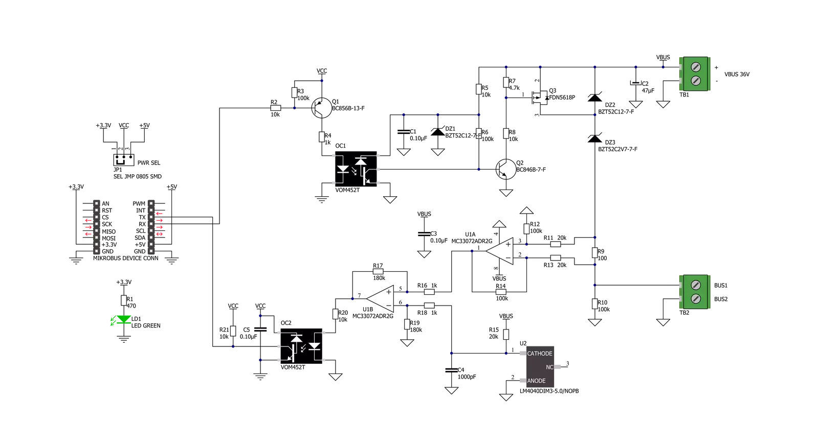
which is a part of the master; when a logical "0" (Space) is sent, the repeater reduces the bus voltage by 12 V to a nominal +24 V at its output. Bits sent in the direction from slave to master are coded by modulating the current consumption of the slave. A logical "1" is represented by a constant (versus voltage, temperature and time) current of up to 1.5 mA, and a logical "0" (Space) by an increased current drain requirement by the slave of additional 11-20 mA. The mark state current can be used to power the interface and possibly the meter or sensor itself. As mentioned above, M-Bus standard has predefined voltage levels and principle of work. In order to achieve that, M-Bus Master click has built in complete solution for master node on the network, based on MC33072ADR2G – monolithic, single supply 3 - 44 V operational amplifier from ON Semiconductor. Besides the operational amplifier, this click board has all other needed components needed to
achieve a complete analog solution which, on its output, fulfils the M-Bus voltage and current predefined specifications. This Click board™ also has VOM452 from Vishay Semiconductors. Theese high speed optocouplers, each consists of a GaAlAs infrared emitting diode, optically coupled with an integrated photo detector and a high speed transistor. The photo detector is junction isolated from the transistor to reduce miller capacitance effects. The open collector output function allows circuit designers to adjust the load conditions when interfacing with different logic systems such as TTL, CMOS, etc. All these features improve the reliability of the whole circuit, while enabling the galvanic isolation. M-Bus Master click offers a selection between 3.3V and 5V operation, with the onboard SMD jumper, labeled as PWR SEL. This allows both 3.3V and 5V MCUs to be interfaced with this Click board™.

Features overview
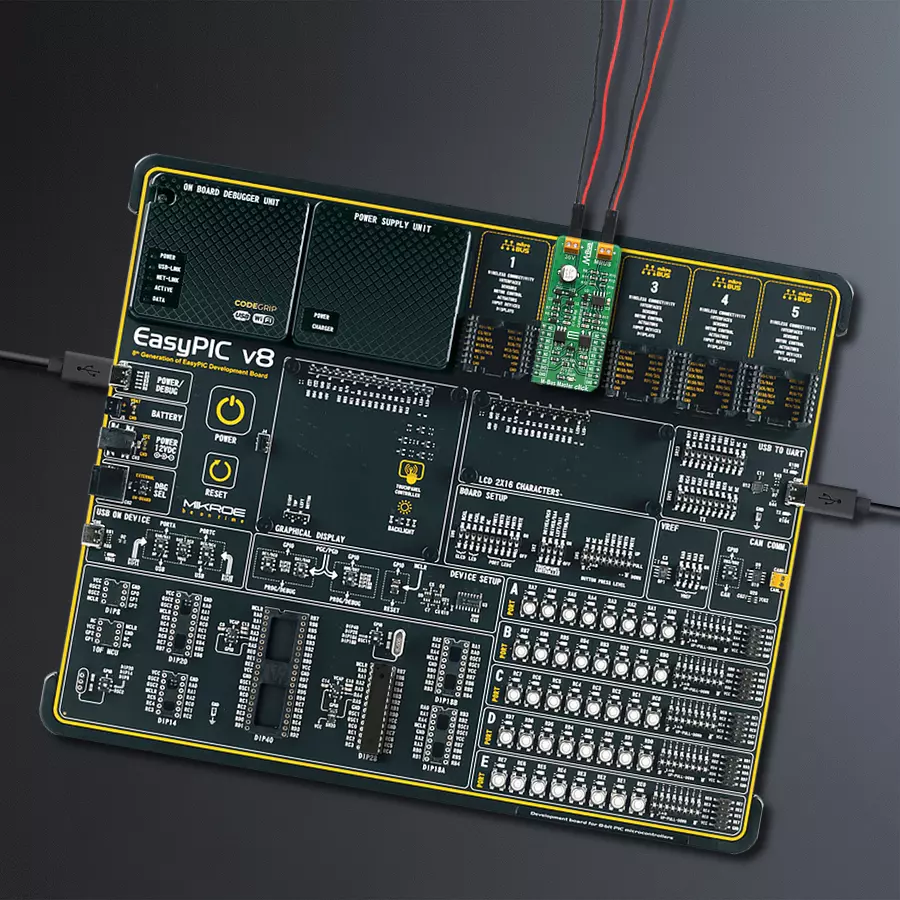
Development board
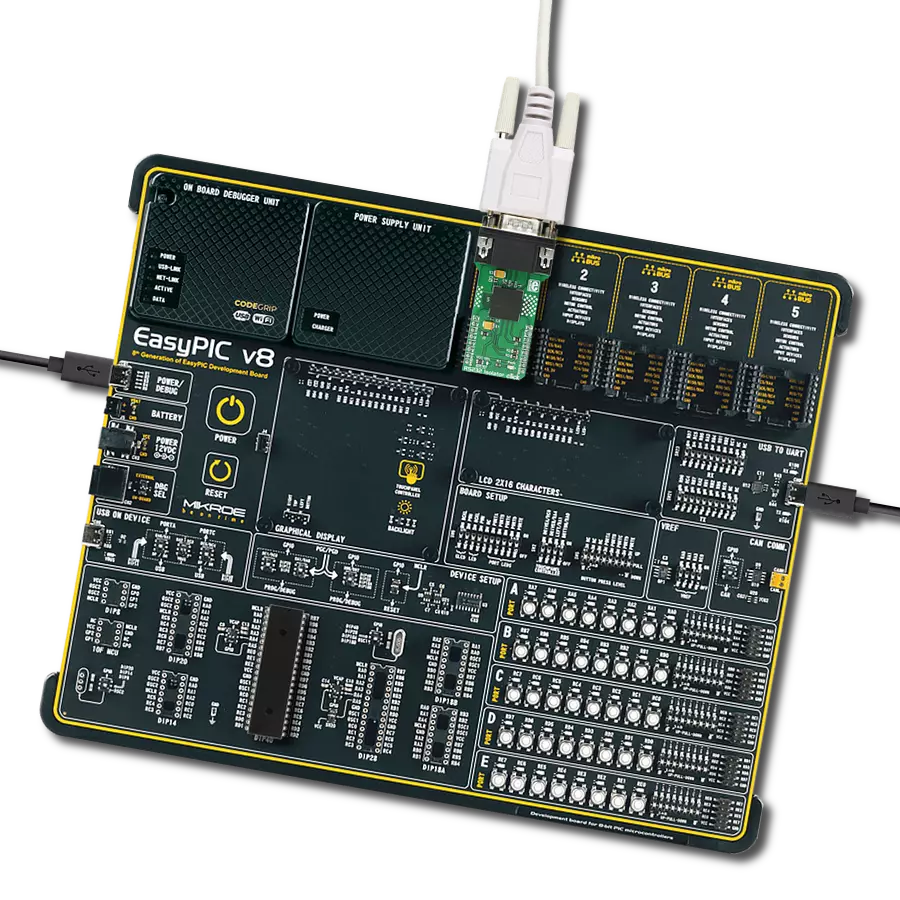
EasyPIC v8 is a development board specially designed for the needs of rapid development of embedded applications. It supports many high pin count 8-bit PIC microcontrollers from Microchip, regardless of their number of pins, and a broad set of unique functions, such as the first-ever embedded debugger/programmer. The development board is well organized and designed so that the end-user has all the necessary elements, such as switches, buttons, indicators, connectors, and others, in one place. Thanks to innovative manufacturing technology, EasyPIC v8 provides a fluid and immersive working experience, allowing access anywhere and under any
circumstances at any time. Each part of the EasyPIC v8 development board contains the components necessary for the most efficient operation of the same board. In addition to the advanced integrated CODEGRIP programmer/debugger module, which offers many valuable programming/debugging options and seamless integration with the Mikroe software environment, the board also includes a clean and regulated power supply module for the development board. It can use a wide range of external power sources, including a battery, an external 12V power supply, and a power source via the USB Type-C (USB-C) connector.
Communication options such as USB-UART, USB DEVICE, and CAN are also included, including the well-established mikroBUS™ standard, two display options (graphical and character-based LCD), and several different DIP sockets. These sockets cover a wide range of 8-bit PIC MCUs, from the smallest PIC MCU devices with only eight up to forty pins. EasyPIC v8 is an integral part of the Mikroe ecosystem for rapid development. Natively supported by Mikroe software tools, it covers many aspects of prototyping and development thanks to a considerable number of different Click boards™ (over a thousand boards), the number of which is growing every day.

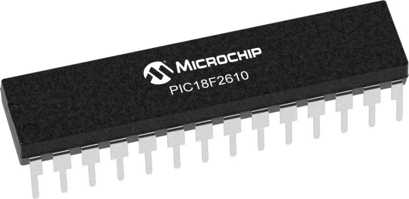
Microcontroller Overview
MCU Card / MCU
Architecture
PIC
MCU Memory (KB)
64
Silicon Vendor
Microchip
Pin count
28
RAM (Bytes)
3968
Used MCU Pins
mikroBUS™ mapper
Take a closer look
Click board™ Schematic
Step by step
Project assembly

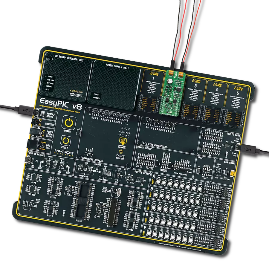
Start by selecting your development board and Click board™. Begin with the EasyPIC v8 as your development board.


Track your results in real time
Application Output
1. Application Output - In Debug mode, the 'Application Output' window enables real-time data monitoring, offering direct insight into execution results. Ensure proper data display by configuring the environment correctly using the provided tutorial.

2. UART Terminal - Use the UART Terminal to monitor data transmission via a USB to UART converter, allowing direct communication between the Click board™ and your development system. Configure the baud rate and other serial settings according to your project's requirements to ensure proper functionality. For step-by-step setup instructions, refer to the provided tutorial.

3. Plot Output - The Plot feature offers a powerful way to visualize real-time sensor data, enabling trend analysis, debugging, and comparison of multiple data points. To set it up correctly, follow the provided tutorial, which includes a step-by-step example of using the Plot feature to display Click board™ readings. To use the Plot feature in your code, use the function: plot(*insert_graph_name*, variable_name);. This is a general format, and it is up to the user to replace 'insert_graph_name' with the actual graph name and 'variable_name' with the parameter to be displayed.

Software Support
Library Description
This library contains API for M-Bus Master Click driver.
Key functions:
mbusmaster_generic_write- Generic write function.mbusmaster_generic_read- Generic read function.
Open Source
Code example
The complete application code and a ready-to-use project are available through the NECTO Studio Package Manager for direct installation in the NECTO Studio. The application code can also be found on the MIKROE GitHub account.
/*!
 * \file
 * \brief MBusMaster Click example
 *
 * # Description
 * This example reads and processes data from M-Bus Master Clicks.
 *
 * The demo application is composed of two sections :
 *
 * ## Application Init
 * Initializes the driver.
 *
 * ## Application Task
 * Depending on the selected mode, it reads all the received data or sends the desired message
 * every 2 seconds.
 *
 * ## Additional Function
 * - mbusmaster_process ( ) - The general process of collecting the received data.
 *
 * @note
 * - M-Bus master communication works at 36v.
 * - This Click acts only as 'master', therefore it must be connected to appropriate 'slave'.
 *
 * \author MikroE Team
 *
 */
// ------------------------------------------------------------------- INCLUDES

#include "board.h"
#include "log.h"
#include "mbusmaster.h"

#define PROCESS_RX_BUFFER_SIZE 500

#define TEXT_TO_SEND "MikroE - M-Bus Master Click board\r\n"

// #define DEMO_APP_RECEIVER
#define DEMO_APP_TRANSMITTER

// ------------------------------------------------------------------ VARIABLES

static mbusmaster_t mbusmaster;
static log_t logger;

// ------------------------------------------------------- ADDITIONAL FUNCTIONS

static void mbusmaster_process ( void )
{
    int32_t rsp_size;

    char uart_rx_buffer[ PROCESS_RX_BUFFER_SIZE ] = { 0 };
    uint8_t check_buf_cnt;

    rsp_size = mbusmaster_generic_read( &mbusmaster, uart_rx_buffer, PROCESS_RX_BUFFER_SIZE );

    if ( rsp_size > 0 )
    {
        for ( uint8_t cnt = 0; cnt < rsp_size; cnt++ )
        {
            log_printf( &logger, "%c", uart_rx_buffer[ cnt ] );
            if ( uart_rx_buffer[ cnt ] == '\n' )
            {
                log_printf( &logger, "--------------------------------\r\n" );
            }
        }
    }
}

// ------------------------------------------------------ APPLICATION FUNCTIONS

void application_init ( void )
{
    log_cfg_t log_cfg;
    mbusmaster_cfg_t cfg;

    /**
     * Logger initialization.
     * Default baud rate: 115200
     * Default log level: LOG_LEVEL_DEBUG
     * @note If USB_UART_RX and USB_UART_TX
     * are defined as HAL_PIN_NC, you will
     * need to define them manually for log to work.
     * See @b LOG_MAP_USB_UART macro definition for detailed explanation.
     */
    LOG_MAP_USB_UART( log_cfg );
    log_init( &logger, &log_cfg );
    log_info( &logger, "---- Application Init ----" );
    Delay_ms ( 100 );

    //  Click initialization.

    mbusmaster_cfg_setup( &cfg );
    MBUSMASTER_MAP_MIKROBUS( cfg, MIKROBUS_1 );
    mbusmaster_init( &mbusmaster, &cfg );
    Delay_ms ( 100 );
}

void application_task ( void )
{
#ifdef DEMO_APP_RECEIVER
    mbusmaster_process( );
#endif

#ifdef DEMO_APP_TRANSMITTER
    mbusmaster_generic_write( &mbusmaster, TEXT_TO_SEND, strlen( TEXT_TO_SEND ) );
    log_info( &logger, "---- Data sent ----" );
    Delay_ms ( 1000 );
    Delay_ms ( 1000 );
#endif
}

int main ( void )
{
    /* Do not remove this line or clock might not be set correctly. */
    #ifdef PREINIT_SUPPORTED
    preinit();
    #endif

    application_init( );

    for ( ; ; )
    {
        application_task( );
    }

    return 0;
}

// ------------------------------------------------------------------------ END