Experience the accuracy you need for confident weight measurement using ZSC31014 and PIC18F26K80
Redefining weight scales
Published Dec 29, 2023
Click board™
Load Cell 4 Click
Dev. board
EasyPIC v7a
Compiler
NECTO Studio
MCU
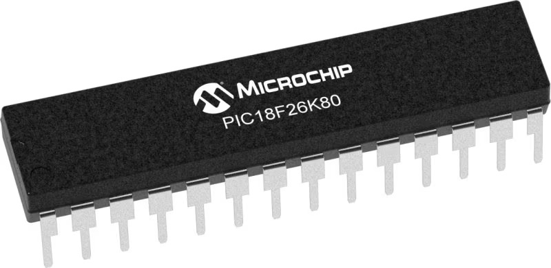
PIC18F26K80
Make daily routines smarter by incorporating our precise weight scale solution
A
A
Hardware Overview
How does it work?
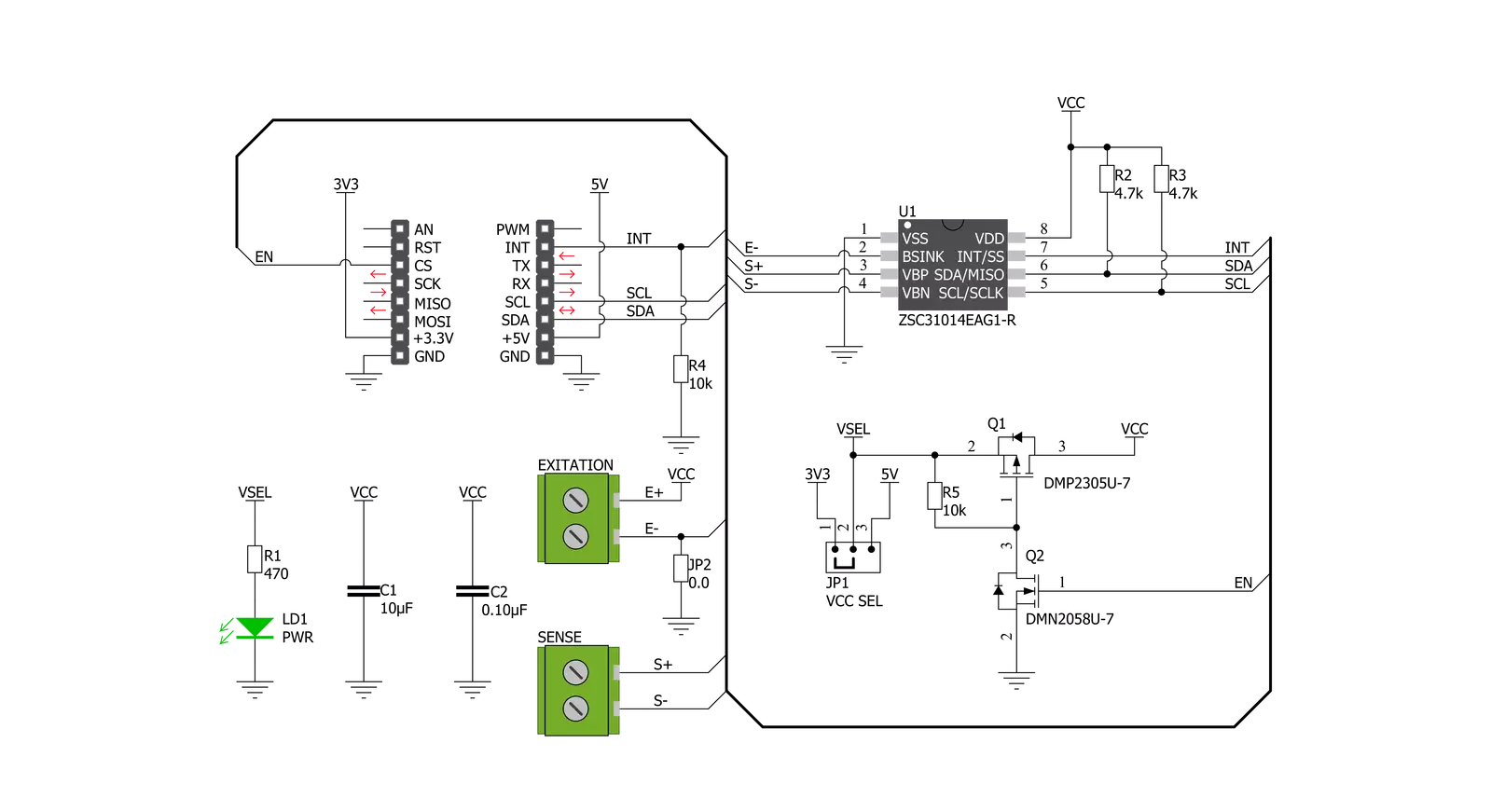
Load Cell 4 Click is based on the ZSC31014, a CMOS integrated circuit for highly accurate amplification and analog-to-digital conversion of differential and half-bridge input signals from Renesas. The ZSC31014 has a fully differential chopper-stabilized preamplifier with eight programmable gain settings (1.5, 3, 6, 12, 24, 48, 96, and 192) through a 14-bit ADC. The resolution of the output depends on the input span and the analog gain setting. The system clock of the ZSC31014 can operate at 1MHz (lower power, better noise performance) or 4MHz (faster sample rates). Internal DSP core uses coefficients stored in EEPROM to calibrate/condition the amplified differential input signal precisely. Temperature can be measured from an internal temperature sensor, which can be calibrated to compensate for the temperature effects of the sensor bridge. After the Power-On
Reset function, the ZSC31014 wakes, and if it receives the Start_CM command during the command window, it goes into Command Mode. This Mode is primarily used in the calibration environment, and during Command Mode, the device executes commands sent by the I2C master. The ZSC31014 remains in Command Mode until it receives the Start_NOM command, which starts the Normal Operation Mode. Operation after the Power-On sequence depends on whether the part is programmed in Sleep Mode or Update Mode. In Sleep Mode, the ZSC31014 waits for commands from the master before taking measurements, while in Update Mode, data is taken at a fixed, selectable rate. Load Cell 4 Click communicates with MCU using the standard I2C 2-Wire interface with a clock frequency from 100 to 400 kHz. The INT pin of the mikroBUS™ socket,
used as an interrupt, rises when new output data is ready and falls when the next I2C communication occurs. It is most useful if the part is configured in Sleep Mode to indicate to the system that a new conversion is ready. Besides, this Click board™ also possesses an Enable pin labeled as EN, routed to the CS pin of the mikroBUS™ socket, which serves to turn the ZSC31014's power supply on/off. This Click board™ can operate with either 3.3V or 5V logic voltage levels selected via the VCC SEL jumper. This way, both 3.3V and 5V capable MCUs can use the communication lines properly. Also, this Click board™ comes equipped with a library containing easy-to-use functions and an example code that can be used as a reference for further development.

Features overview
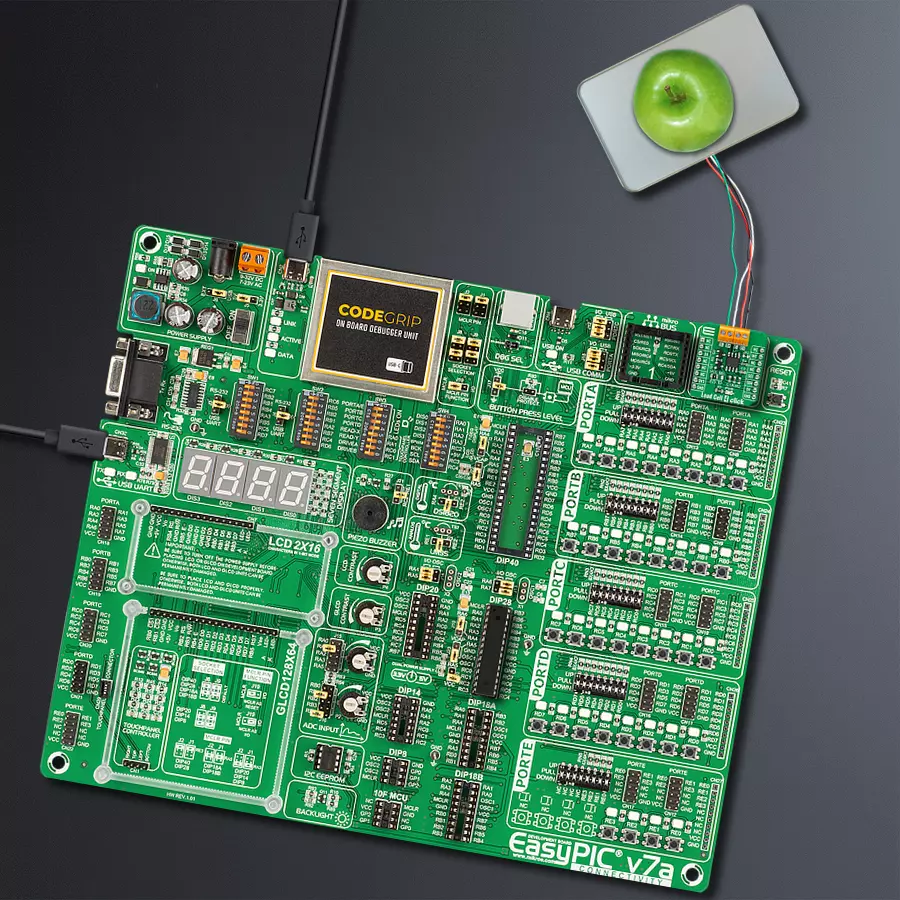
Development board
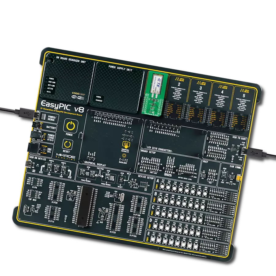
EasyPIC v7a is the seventh generation of PIC development boards specially designed for the needs of rapid development of embedded applications. It supports a wide range of 8-bit PIC microcontrollers from Microchip and has a broad set of unique functions, such as the first-ever embedded debugger/programmer over USB-C. The development board is well organized and designed so that the end-user has all the necessary elements in one place, such as switches, buttons, indicators, connectors, and others. With four different connectors for each port, EasyPIC v7a allows you to connect accessory boards, sensors, and custom electronics more efficiently than ever. Each part of the EasyPIC v7a development board
contains the components necessary for the most efficient operation of the same board. In addition to the advanced integrated CODEGRIP programmer/debugger module, which offers many valuable programming/debugging options and seamless integration with the Mikroe software environment, the board also includes a clean and regulated power supply module for the development board. It can use various external power sources, including an external 12V power supply, 7-23V AC or 9-32V DC via DC connector/screw terminals, and a power source via the USB Type-C (USB-C) connector. Communication options such as USB-UART and RS-232 are also included, alongside the well-
established mikroBUS™ standard, three display options (7-segment, graphical, and character-based LCD), and several different DIP sockets. These sockets cover a wide range of 8-bit PIC MCUs, from PIC10F, PIC12F, PIC16F, PIC16Enh, PIC18F, PIC18FJ, and PIC18FK families. EasyPIC v7a is an integral part of the Mikroe ecosystem for rapid development. Natively supported by Mikroe software tools, it covers many aspects of prototyping and development thanks to a considerable number of different Click boards™ (over a thousand boards), the number of which is growing every day.

Microcontroller Overview
MCU Card / MCU
Architecture
PIC
MCU Memory (KB)
64
Silicon Vendor
Microchip
Pin count
28
RAM (Bytes)
3648
Used MCU Pins
mikroBUS™ mapper
Take a closer look
Click board™ Schematic
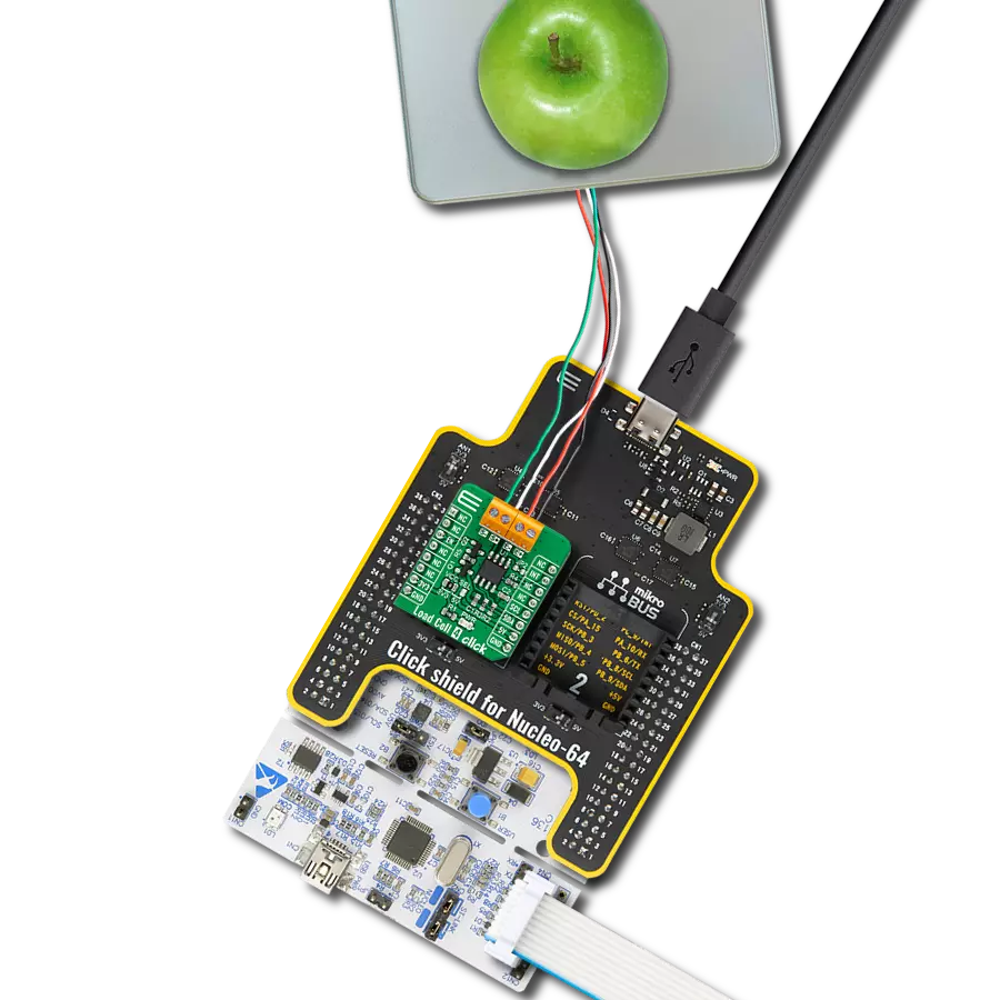
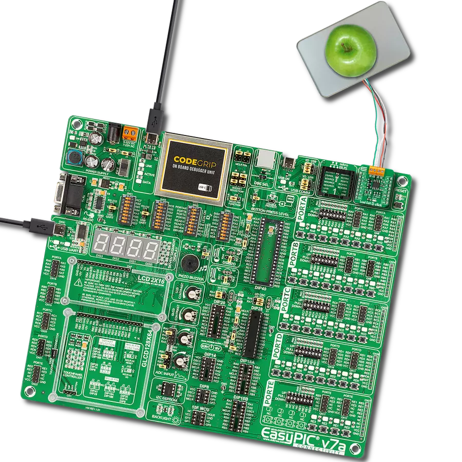
Step by step
Project assembly

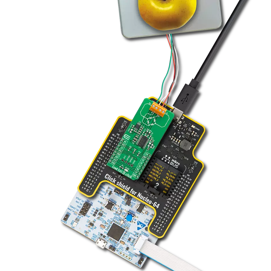
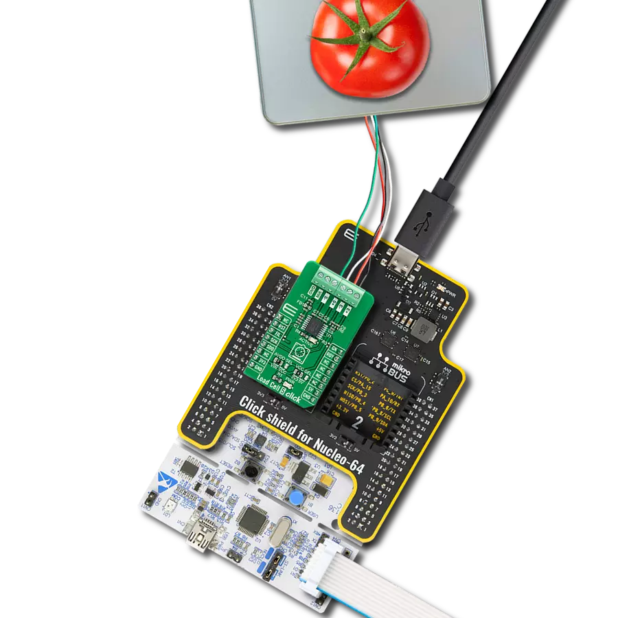
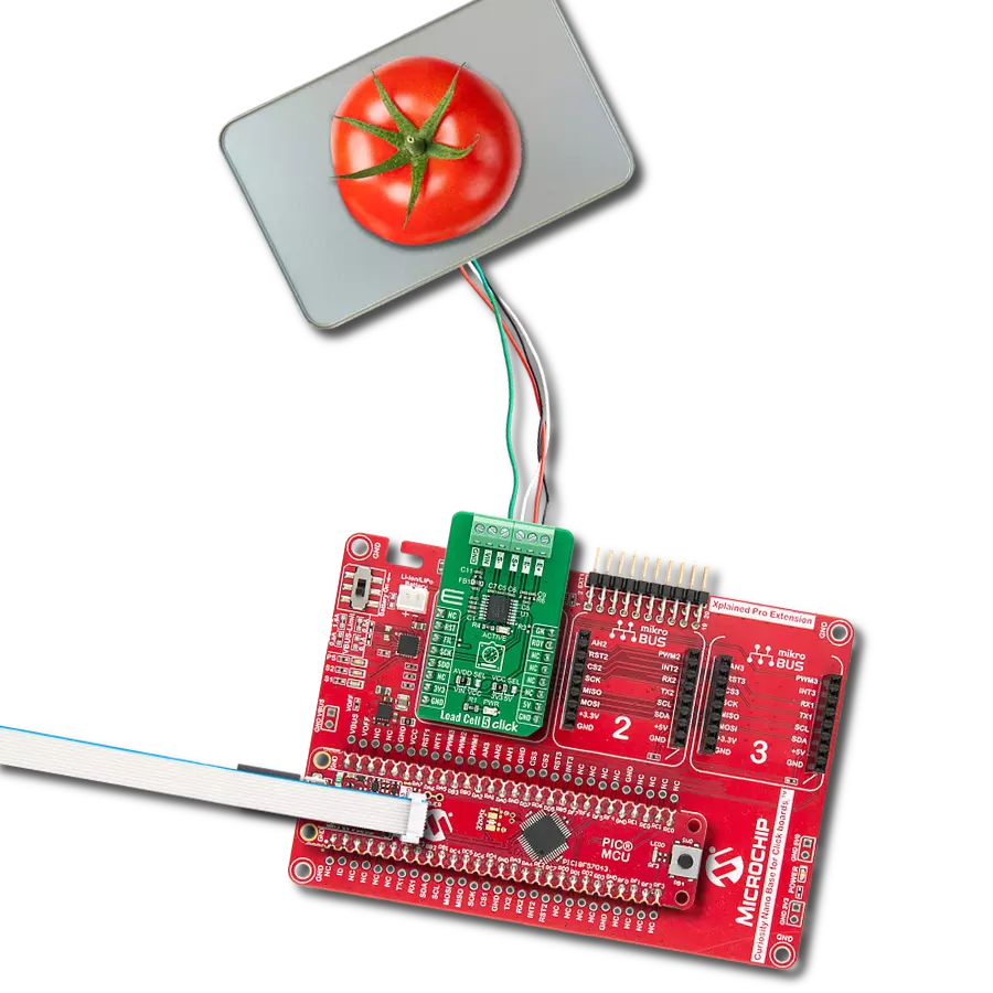
Start by selecting your development board and Click board™. Begin with the EasyPIC v7a as your development board.


Track your results in real time
Application Output
1. Application Output - In Debug mode, the 'Application Output' window enables real-time data monitoring, offering direct insight into execution results. Ensure proper data display by configuring the environment correctly using the provided tutorial.

2. UART Terminal - Use the UART Terminal to monitor data transmission via a USB to UART converter, allowing direct communication between the Click board™ and your development system. Configure the baud rate and other serial settings according to your project's requirements to ensure proper functionality. For step-by-step setup instructions, refer to the provided tutorial.

3. Plot Output - The Plot feature offers a powerful way to visualize real-time sensor data, enabling trend analysis, debugging, and comparison of multiple data points. To set it up correctly, follow the provided tutorial, which includes a step-by-step example of using the Plot feature to display Click board™ readings. To use the Plot feature in your code, use the function: plot(*insert_graph_name*, variable_name);. This is a general format, and it is up to the user to replace 'insert_graph_name' with the actual graph name and 'variable_name' with the parameter to be displayed.

Software Support
Library Description
This library contains API for Load Cell 4 Click driver.
Key functions:
loadcell4_power_dev- Enable power functionloadcell4_tare- Tare the scales functionloadcell4_get_weight- Get weight function.
Open Source
Code example
The complete application code and a ready-to-use project are available through the NECTO Studio Package Manager for direct installation in the NECTO Studio. The application code can also be found on the MIKROE GitHub account.
/*!
 * @file main.c
 * @brief LoadCell4 Click example
 *
 * # Description
 * This is an example that demonstrates the use of the Load Cell 4 Click board.
 *
 * The demo application is composed of two sections :
 *
 * ## Application Init
 * Initializes I2C driver and performs the power on.
 * Sets tare the scale, calibrate scale and start measurements.
 *
 * ## Application Task
 * The Load Cell 4 Click board can be used to measure weight,
 * shows the measurement of scales in grams [ g ].
 * Results are being sent to the Usart Terminal where you can track their changes.
 * All data logs write on USB uart changes for every 4 sec.
 *
 * @author Stefan Ilic
 *
 */

#include "board.h"
#include "log.h"
#include "loadcell4.h"

static loadcell4_t loadcell4;
static log_t logger;

static loadcell4_data_t cell_data;
static float weight_val;

void application_init ( void ) {
    log_cfg_t log_cfg;  /**< Logger config object. */
    loadcell4_cfg_t loadcell4_cfg;  /**< Click config object. */

    /**
     * Logger initialization.
     * Default baud rate: 115200
     * Default log level: LOG_LEVEL_DEBUG
     * @note If USB_UART_RX and USB_UART_TX
     * are defined as HAL_PIN_NC, you will
     * need to define them manually for log to work.
     * See @b LOG_MAP_USB_UART macro definition for detailed explanation.
     */
    LOG_MAP_USB_UART( log_cfg );
    log_init( &logger, &log_cfg );
    log_info( &logger, " Application Init " );

    // Click initialization.
    loadcell4_cfg_setup( &loadcell4_cfg );
    LOADCELL4_MAP_MIKROBUS( loadcell4_cfg, MIKROBUS_1 );
    err_t init_flag = loadcell4_init( &loadcell4, &loadcell4_cfg );
    if ( I2C_MASTER_ERROR == init_flag ) {
        log_error( &logger, " Application Init Error. " );
        log_info( &logger, " Please, run program again... " );

        for ( ; ; );
    }
    loadcell4_default_cfg ( &loadcell4 );

    loadcell4_power_dev( &loadcell4, LOADCELL4_PWR_ON );
    Delay_ms ( 500 );

    log_printf( &logger, "-------------------------\r\n" );
    log_printf( &logger, "     ~~~  STEP 1  ~~~    \r\n" );
    log_printf( &logger, "-------------------------\r\n" );
    log_printf( &logger, "     Tare the scale :    \r\n" );
    log_printf( &logger, "- - - - - - - - - - - - -\r\n" );
    log_printf( &logger, " >> Remove all object << \r\n" );
    log_printf( &logger, "- - - - - - - - - - - - -\r\n" );
    log_printf( &logger, " In the following 10 sec \r\n" );
    log_printf( &logger, " please remove all object\r\n" );
    log_printf( &logger, "     from the scale.     \r\n" );
    // 10 seconds delay
    Delay_ms ( 1000 );
    Delay_ms ( 1000 );
    Delay_ms ( 1000 );
    Delay_ms ( 1000 );
    Delay_ms ( 1000 );
    Delay_ms ( 1000 );
    Delay_ms ( 1000 );
    Delay_ms ( 1000 );
    Delay_ms ( 1000 );
    Delay_ms ( 1000 );

    log_printf( &logger, "-------------------------\r\n" );
    log_printf( &logger, "    Start tare scales    \r\n" );
    loadcell4_tare( &loadcell4, &cell_data );
    Delay_ms ( 500 );

    log_printf( &logger, "-------------------------\r\n" );
    log_printf( &logger, "   Tarring is complete   \r\n" );

    log_printf( &logger, "-------------------------\r\n" );
    log_printf( &logger, "     ~~~  STEP 2  ~~~    \r\n" );
    log_printf( &logger, "-------------------------\r\n" );
    log_printf( &logger, "    Calibrate Scale :    \r\n" );
    log_printf( &logger, "- - - - - - - - - - - - -\r\n" );
    log_printf( &logger, "   >>> Load etalon <<<   \r\n" );
    log_printf( &logger, "- - - - - - - - - - - - -\r\n" );
    log_printf( &logger, " In the following 10 sec \r\n" );
    log_printf( &logger, "place 100 g weight etalon\r\n" );
    log_printf( &logger, "    on the scale for     \r\n" );
    log_printf( &logger, "   calibration purpose.  \r\n" );
    // 10 seconds delay
    Delay_ms ( 1000 );
    Delay_ms ( 1000 );
    Delay_ms ( 1000 );
    Delay_ms ( 1000 );
    Delay_ms ( 1000 );
    Delay_ms ( 1000 );
    Delay_ms ( 1000 );
    Delay_ms ( 1000 );
    Delay_ms ( 1000 );
    Delay_ms ( 1000 );

    log_printf( &logger, "-------------------------\r\n" );
    log_printf( &logger, "    Start calibration    \r\n" );

    if ( loadcell4_calibration( &loadcell4, LOADCELL4_WEIGHT_100G, &cell_data ) == LOADCELL4_OK ) {
        log_printf( &logger, "-------------------------\r\n" );
        log_printf( &logger, "    Calibration  Done    \r\n" );
        log_printf( &logger, "- - - - - - - - - - - - -\r\n" );
        log_printf( &logger, "  >>> Remove etalon <<<  \r\n" );
        log_printf( &logger, "- - - - - - - - - - - - -\r\n" );
        log_printf( &logger, " In the following 10 sec \r\n" );
        log_printf( &logger, "   remove 100 g weight   \r\n" );
        log_printf( &logger, "   etalon on the scale.  \r\n" );
        // 10 seconds delay
        Delay_ms ( 1000 );
        Delay_ms ( 1000 );
        Delay_ms ( 1000 );
        Delay_ms ( 1000 );
        Delay_ms ( 1000 );
        Delay_ms ( 1000 );
        Delay_ms ( 1000 );
        Delay_ms ( 1000 );
        Delay_ms ( 1000 );
        Delay_ms ( 1000 );
    } else {
        log_printf( &logger, "-------------------------\r\n" );
        log_printf( &logger, "   Calibration  Error   \r\n" );
        for ( ; ; );
    }

    log_printf( &logger, "-------------------------\r\n" );
    log_printf( &logger, "   Start measurements :  \r\n" );
    log_printf( &logger, "-------------------------\r\n" );
}

void application_task ( void ) {
    weight_val = loadcell4_get_weight( &loadcell4, &cell_data );
    log_printf( &logger, "     Weight : %.2f g \r\n", weight_val );
    Delay_ms ( 100 );
}

int main ( void )
{
    /* Do not remove this line or clock might not be set correctly. */
    #ifdef PREINIT_SUPPORTED
    preinit();
    #endif

    application_init( );

    for ( ; ; )
    {
        application_task( );
    }

    return 0;
}

// ------------------------------------------------------------------------ END