Experience the future of control and calibration with our POT and PIC18LF27K40
Fine-tune, better performance: Redefining control with trimmers

Published Nov 01, 2023
Click board™
POT 4 Click
Dev. board
EasyPIC v7
Compiler
NECTO Studio
MCU
PIC18LF27K40
Our trimmer potentiometer solution is engineered to revolutionize control, providing fine-tuning capabilities for precise adjustments in a wide range of devices and applications
A
A
Hardware Overview
How does it work?
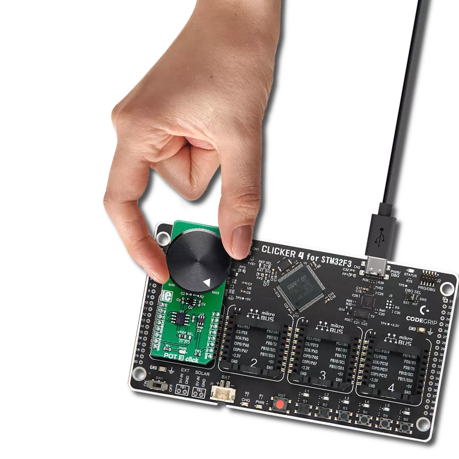
POT 4 Click is based on the PRS11R-425F-S103B1, a high-quality rotary 10k potentiometer from Bourns providing very accurate voltage output. The PDB081-P10-103B1 features a small form factor, offers a push-on momentary switch, a flatted shaft style, and a wide operating temperature range, withstanding 50V maximum voltage. Typical applications include consumer white goods, test and measurement equipment, communications and laboratory equipment, and other applications requiring an analog or digitized control voltage. The output of the potentiometer is brought to the non-inverting input of the OPA344, a rail-to-rail
operational amplifier from Texas Instruments, used as a stable unity gain buffer, providing a constant input and output impedance. Without a buffer, the variable impedance would affect the reference voltage. Therefore, the OPA344 ensures good stability of the circuit. A buffered signal can be converted to a digital value using the MCP3221, a successive approximation A/D converter with a 12-bit resolution from Microchip using a 2-wire I2C compatible interface, or can be sent directly to an analog pin of the mikroBUS™ socket labeled as AN. The selection can be performed by using an onboard SMD switch labeled as VIN SEL, placing it
in an appropriate position marked as AN or ADC. Noting that the PRS11R-425F-S103B1 has an optional push momentary switch, this Click board™ also has an interrupt that will signal to users when this feature is used. This Click board™ can operate with either 3.3V or 5V logic voltage levels selected via the VCC SEL jumper. This way, both 3.3V and 5V capable MCUs can use the communication lines properly. Also, this Click board™ comes equipped with a library containing easy-to-use functions and an example code that can be used as a reference for further development.

Features overview
Development board
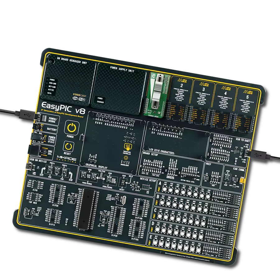
EasyPIC v7 is the seventh generation of PIC development boards specially designed to develop embedded applications rapidly. It supports a wide range of 8-bit PIC microcontrollers from Microchip and has a broad set of unique functions, such as a powerful onboard mikroProg programmer and In-Circuit debugger over USB-B. The development board is well organized and designed so that the end-user has all the necessary elements in one place, such as switches, buttons, indicators, connectors, and others. With four different connectors for each port, EasyPIC v7 allows you to connect accessory boards, sensors, and custom electronics more efficiently than ever. Each part of
the EasyPIC v7 development board contains the components necessary for the most efficient operation of the same board. An integrated mikroProg, a fast USB 2.0 programmer with mikroICD hardware In-Circuit Debugger, offers many valuable programming/debugging options and seamless integration with the Mikroe software environment. Besides it also includes a clean and regulated power supply block for the development board. It can use various external power sources, including an external 12V power supply, 7-23V AC or 9-32V DC via DC connector/screw terminals, and a power source via the USB Type-B (USB-B) connector. Communication options such as
USB-UART and RS-232 are also included, alongside the well-established mikroBUS™ standard, three display options (7-segment, graphical, and character-based LCD), and several different DIP sockets. These sockets cover a wide range of 8-bit PIC MCUs, from PIC10F, PIC12F, PIC16F, PIC16Enh, PIC18F, PIC18FJ, and PIC18FK families. EasyPIC v7 is an integral part of the Mikroe ecosystem for rapid development. Natively supported by Mikroe software tools, it covers many aspects of prototyping and development thanks to a considerable number of different Click boards™ (over a thousand boards), the number of which is growing every day.

Microcontroller Overview
MCU Card / MCU
Architecture
PIC
MCU Memory (KB)
128
Silicon Vendor
Microchip
Pin count
28
RAM (Bytes)
3728
Used MCU Pins
mikroBUS™ mapper
Take a closer look
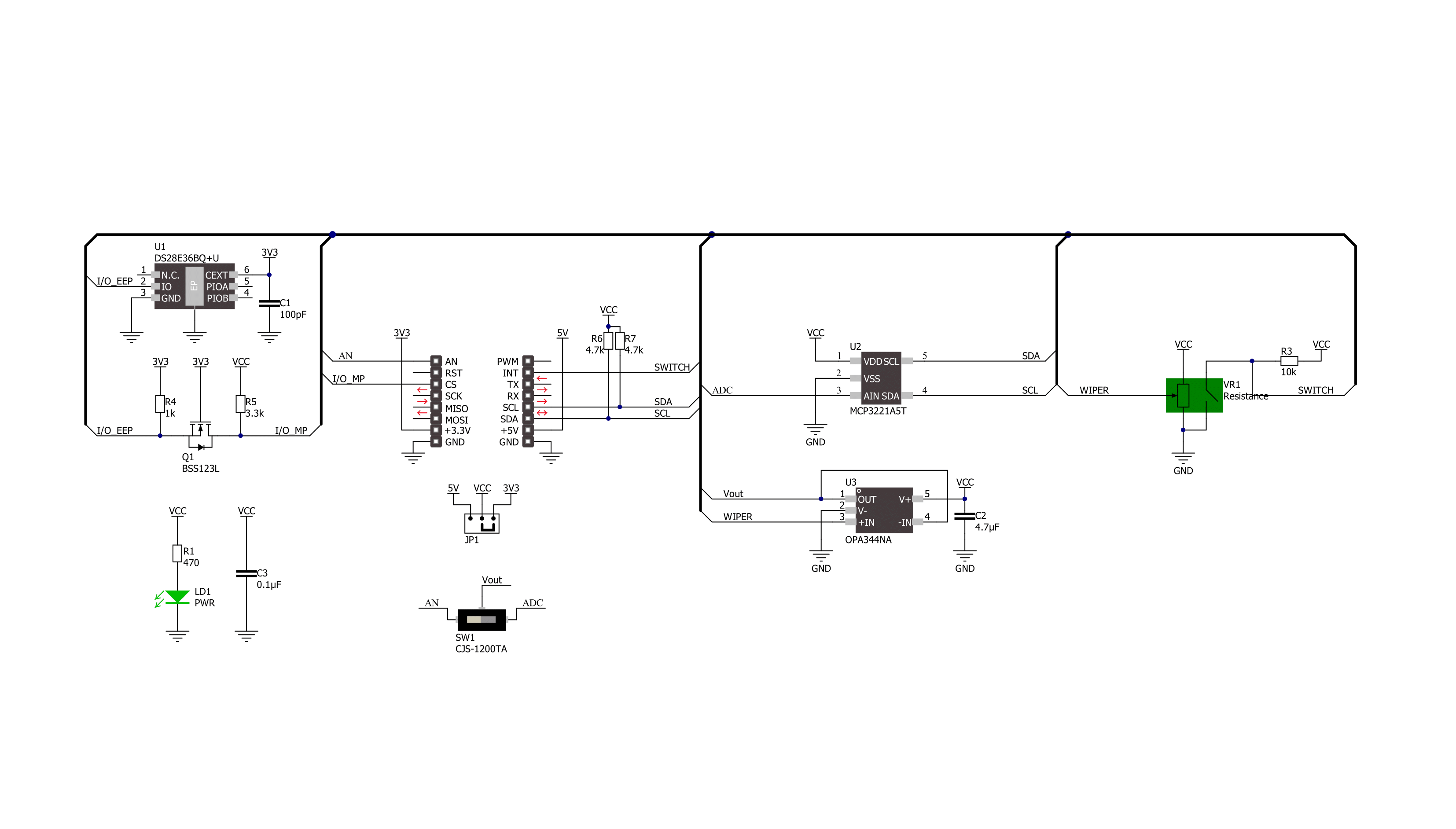
Click board™ Schematic
Step by step
Project assembly

Start by selecting your development board and Click board™. Begin with the EasyPIC v7 as your development board.


Software Support
Library Description
This library contains API for POT 4 Click driver.
Key functions:
pot4_get_switch_pin- This function returns the switch (SW) pin logic statepot4_read_voltage- This function reads raw ADC value and converts it to proportional voltage levelpot4_convert_voltage_to_percents- This function converts analog voltage to potentiometer position in percents
Open Source
Code example
The complete application code and a ready-to-use project are available through the NECTO Studio Package Manager for direct installation in the NECTO Studio. The application code can also be found on the MIKROE GitHub account.
/*!
 * @file main.c
 * @brief POT 4 Click Example.
 *
 * # Description
 * This example demonstrates the use of POT 4 Click board by reading and displaying
 * the potentiometer position.
 *
 * The demo application is composed of two sections :
 *
 * ## Application Init
 * Initializes the driver and logger.
 *
 * ## Application Task
 * Reads and displays on the USB UART the potentiometer position in forms of voltage and
 * percents once per second only when the potentiometer switch is active.
 *
 * @author Stefan Filipovic
 *
 */

#include "board.h"
#include "log.h"
#include "pot4.h"

static pot4_t pot4;     /**< POT 4 Click driver object. */
static log_t logger;    /**< Logger object. */

void application_init ( void )
{
    log_cfg_t log_cfg;  /**< Logger config object. */
    pot4_cfg_t pot4_cfg;  /**< Click config object. */

    /**
     * Logger initialization.
     * Default baud rate: 115200
     * Default log level: LOG_LEVEL_DEBUG
     * @note If USB_UART_RX and USB_UART_TX
     * are defined as HAL_PIN_NC, you will
     * need to define them manually for log to work.
     * See @b LOG_MAP_USB_UART macro definition for detailed explanation.
     */
    LOG_MAP_USB_UART( log_cfg );
    log_init( &logger, &log_cfg );
    log_info( &logger, " Application Init " );

    // Click initialization.
    pot4_cfg_setup( &pot4_cfg );
    POT4_MAP_MIKROBUS( pot4_cfg, MIKROBUS_1 );
    err_t init_flag = pot4_init( &pot4, &pot4_cfg );
    if ( ( ADC_ERROR == init_flag ) || ( I2C_MASTER_ERROR == init_flag ) )
    {
        log_error( &logger, " Communication init." );
        for ( ; ; );
    }

    log_info( &logger, " Application Task " );
}

void application_task ( void )
{
    if ( !pot4_get_switch_pin ( &pot4 ) )
    {
        float voltage = 0;
        if ( POT4_OK == pot4_read_voltage ( &pot4, &voltage ) )
        {
            log_printf( &logger, " AN Voltage : %.3f V\r\n", voltage );
            log_printf( &logger, " Potentiometer : %u %%\r\n\n",
                        ( uint16_t ) pot4_convert_voltage_to_percents ( &pot4, voltage ) );
            Delay_ms ( 1000 );
        }
    }
}

int main ( void )
{
    /* Do not remove this line or clock might not be set correctly. */
    #ifdef PREINIT_SUPPORTED
    preinit();
    #endif

    application_init( );

    for ( ; ; )
    {
        application_task( );
    }

    return 0;
}

// ------------------------------------------------------------------------ END
Additional Support
Resources
Category:Potentiometers