Provide reliable and precise control over the voltage output with RK1191110001 and STM32F031K6
Ensure that even the slightest trims are accurately digitized and reflected in the voltage output

Published Oct 01, 2024
Click board™
POT 3 Click
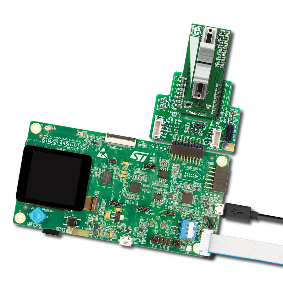
Dev. board
Nucleo 32 with STM32F031K6 MCU
Compiler
NECTO Studio
MCU
STM32F031K6
Translate physical POT adjustments into precise voltage reference outputs suitable for sensitive projects in industrial and hobbyist settings, where ease of use and reliability are paramount
A
A
Hardware Overview
How does it work?
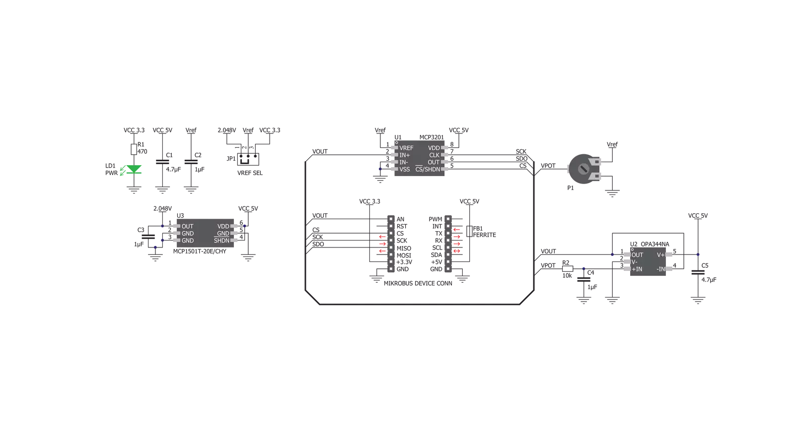
POT 3 Click is based on the MCP1501, a precision voltage reference IC from Microchip is used to provide the voltage of 2.048V. This voltage is routed to the small SMD jumper labeled as VREF SEL. By moving the jumper to the 2V position, 2.048V will be applied to one end of the potentiometer. Otherwise, the potentiometer will be connected to the 3.3V rail of the mikroBUS™. The other end of the potentiometer is tied to GND, allowing to select voltage from 0V to VREF (from 0 to 2.048V or from 0 to 3.3V ranges). The adjustable voltage is available on both AN pin of the mikroBUS™ and to the + input pin of the MCP3201. The potentiometer itself is labeled as RK1191110001. It is a high-quality potentiometer from Alps Alpine. This company is otherwise known for their high-quality electromechanical
components, used in many industries. The potentiometer has a carbon-based resistive surface with the resistance of 10 kΩ. It is a single-turn linear potentiometer, with 50% of resistance achieved when in the middle position. Its turning knob is not fixed: the potentiometer has 15mm shaft and a turning knob with the matching shape is delivered in the package with the Click board™. The output of the potentiometer is fed to the non-inverting input of the OPA344, a rail-to-rail single supply operational amplifier, from Texas Instruments. This operational amplifier is a perfect choice for this design, as it allows rail-to-rail operation, uses a single power supply of 5V, and has a stable unity gain. The OPA344 is used as a buffer, providing a constant input and output impedance. Without buffer, variable impedance
would affect the reference voltage. The reference voltage IC can provide less than 10 mA, with the significant voltage drop for output currents exceeding 2 mA. Therefore, the OPA344 ensures good stability of the circuit. The second section of this click board™ consists of the MCP3201 IC, a well known 12-bit ADC from Microchip. The potentiometer end terminals are connected between GND and the VREF, while the buffered voltage from the wiper is connected to the IN+ pin of the MCP3201. VREF is also connected to the reference voltage input pin of the MCP3201. That way, the whole range of the ADC is always used, regardless the chosen VREF voltage. The MCP3201 has its SPI lines routed to the mikroBUS™ so that the values can be read easily by the MCU.

Features overview
Development board
Nucleo 32 with STM32F031K6 MCU board provides an affordable and flexible platform for experimenting with STM32 microcontrollers in 32-pin packages. Featuring Arduino™ Nano connectivity, it allows easy expansion with specialized shields, while being mbed-enabled for seamless integration with online resources. The
board includes an on-board ST-LINK/V2-1 debugger/programmer, supporting USB reenumeration with three interfaces: Virtual Com port, mass storage, and debug port. It offers a flexible power supply through either USB VBUS or an external source. Additionally, it includes three LEDs (LD1 for USB communication, LD2 for power,
and LD3 as a user LED) and a reset push button. The STM32 Nucleo-32 board is supported by various Integrated Development Environments (IDEs) such as IAR™, Keil®, and GCC-based IDEs like AC6 SW4STM32, making it a versatile tool for developers.

Microcontroller Overview
MCU Card / MCU

Architecture
ARM Cortex-M0
MCU Memory (KB)
32
Silicon Vendor
STMicroelectronics
Pin count
32
RAM (Bytes)
4096
You complete me!
Accessories
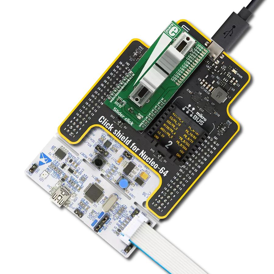
Click Shield for Nucleo-32 is the perfect way to expand your development board's functionalities with STM32 Nucleo-32 pinout. The Click Shield for Nucleo-32 provides two mikroBUS™ sockets to add any functionality from our ever-growing range of Click boards™. We are fully stocked with everything, from sensors and WiFi transceivers to motor control and audio amplifiers. The Click Shield for Nucleo-32 is compatible with the STM32 Nucleo-32 board, providing an affordable and flexible way for users to try out new ideas and quickly create prototypes with any STM32 microcontrollers, choosing from the various combinations of performance, power consumption, and features. The STM32 Nucleo-32 boards do not require any separate probe as they integrate the ST-LINK/V2-1 debugger/programmer and come with the STM32 comprehensive software HAL library and various packaged software examples. This development platform provides users with an effortless and common way to combine the STM32 Nucleo-32 footprint compatible board with their favorite Click boards™ in their upcoming projects.

Used MCU Pins
mikroBUS™ mapper
Take a closer look
Click board™ Schematic
Step by step
Project assembly

Start by selecting your development board and Click board™. Begin with the Nucleo 32 with STM32F031K6 MCU as your development board.


Track your results in real time
Application Output
1. Application Output - In Debug mode, the 'Application Output' window enables real-time data monitoring, offering direct insight into execution results. Ensure proper data display by configuring the environment correctly using the provided tutorial.

2. UART Terminal - Use the UART Terminal to monitor data transmission via a USB to UART converter, allowing direct communication between the Click board™ and your development system. Configure the baud rate and other serial settings according to your project's requirements to ensure proper functionality. For step-by-step setup instructions, refer to the provided tutorial.

3. Plot Output - The Plot feature offers a powerful way to visualize real-time sensor data, enabling trend analysis, debugging, and comparison of multiple data points. To set it up correctly, follow the provided tutorial, which includes a step-by-step example of using the Plot feature to display Click board™ readings. To use the Plot feature in your code, use the function: plot(*insert_graph_name*, variable_name);. This is a general format, and it is up to the user to replace 'insert_graph_name' with the actual graph name and 'variable_name' with the parameter to be displayed.

Software Support
Library Description
This library contains API for POT 3 Click driver.
Key functions:
pot3_read_adc- This function reads the result of AD conversionpot3_read_avg_adc- This function reads the averaged result of AD conversionspot3_get_vout- This function returns VOUT value calculated to millivolts
Open Source
Code example
The complete application code and a ready-to-use project are available through the NECTO Studio Package Manager for direct installation in the NECTO Studio. The application code can also be found on the MIKROE GitHub account.
/*!
 * \file
 * \brief Pot3 Click example
 *
 * # Description
 * This application reads voltage value, calculates it to millivolts and then
 * logs it to the uart terminal.
 *
 * The demo application is composed of two sections :
 *
 * ## Application Init
 * Initializes devices module.
 *
 * ## Application Task
 * Reads VOUT value calculated to millivolts with 2000 conversions
 * included in one measurement cycle.
 *
 *
 * \author MikroE Team
 *
 */
// ------------------------------------------------------------------- INCLUDES

#include "board.h"
#include "log.h"
#include "pot3.h"

// ------------------------------------------------------------------ VARIABLES

static pot3_t pot3;
static log_t logger;

static uint16_t voltage_mv;
static uint16_t voltage_old;

// ------------------------------------------------------ APPLICATION FUNCTIONS

void application_init ( void )
{
    log_cfg_t log_cfg;
    pot3_cfg_t pot3_cfg;

    /**
     * Logger initialization.
     * Default baud rate: 115200
     * Default log level: LOG_LEVEL_DEBUG
     * @note If USB_UART_RX and USB_UART_TX
     * are defined as HAL_PIN_NC, you will
     * need to define them manually for log to work.
     * See @b LOG_MAP_USB_UART macro definition for detailed explanation.
     */
    LOG_MAP_USB_UART( log_cfg );
    log_init( &logger, &log_cfg );
    log_info( &logger, "---- Application Init ----" );

    //  Click initialization.

    pot3_cfg_setup( &pot3_cfg );
    POT3_MAP_MIKROBUS( pot3_cfg, MIKROBUS_1 );
    pot3_init( &pot3, &pot3_cfg );

	voltage_old = 0;
}

void application_task ( void )
{
	voltage_mv = pot3_get_vout( &pot3, POT3_VREF_2V, 2000);

	if (voltage_mv != voltage_old)
	{
		log_printf(&logger, " VOUT : %d mV\r\n", voltage_mv);
	}

	voltage_old = voltage_mv;
}

int main ( void )
{
    /* Do not remove this line or clock might not be set correctly. */
    #ifdef PREINIT_SUPPORTED
    preinit();
    #endif

    application_init( );

    for ( ; ; )
    {
        application_task( );
    }

    return 0;
}

// ------------------------------------------------------------------------ END