Manage and optimize pressure data like a pro with LPS27HHW and PIC18F24K50
The power of precision in the palm of your hand

Published Dec 29, 2023
Click board™
Pressure 15 Click
Dev. board
EasyPIC v7
Compiler
NECTO Studio
MCU
PIC18F24K50
Witness how digital pressure sensors lead the way in innovation and accuracy across a wide spectrum of uses
A
A
Hardware Overview
How does it work?
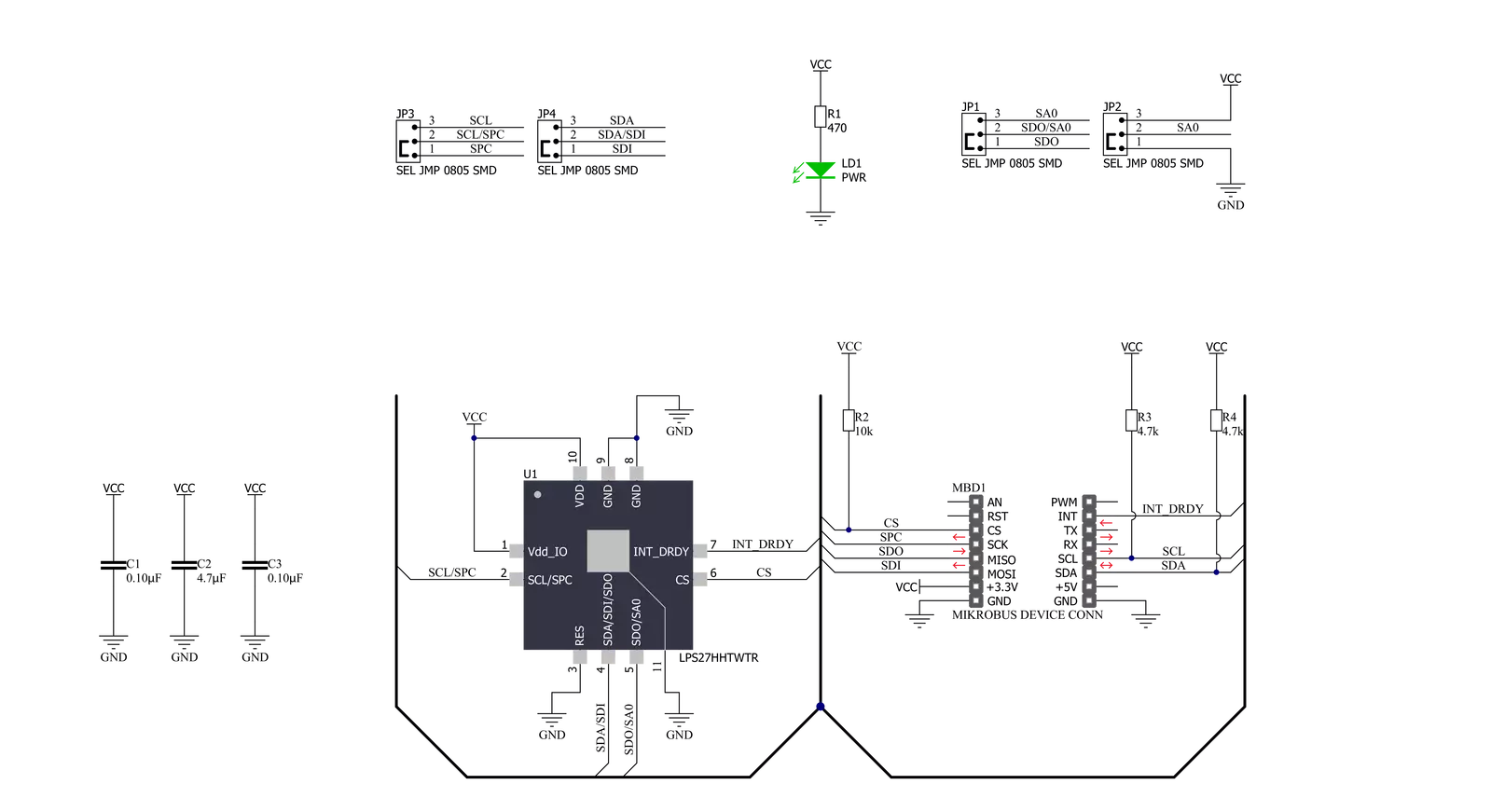
Pressure 15 Click is based on the LPS27HHW, a high-resolution, ultra-compact piezoresistive absolute pressure sensor that functions as a digital output barometer from STMicroelectronics. The complete device includes a sensing element based on a piezoresistive Wheatstone bridge approach, which detects absolute pressure in a 260 up to 1260hPa range and a serial interface that communicates a digital signal from the sensing element to the application. The LPS27HHW has a unique cylindrical package solution with an entire metal lid assembled on a ceramic substrate. When pressure is applied, the membrane deflection induces an imbalance in the Wheatstone
bridge piezoresistance, whose output signal is then converted by the chosen serial interface. Pressure 15 Click allows both I2C and SPI interface with a maximum frequency of 100kHz in Standard and 400kHz in Fast mode for I2C and 8MHz for SPI communication. The selection can be made by positioning SMD jumpers labeled COMM SEL to an appropriate position. Note that all the jumpers' positions must be on the same side, or the Click board™ may become unresponsive. While the I2C interface is selected, the LPS27HHW allows the choice of the least significant bit (LSB) of its I2C slave address using the SMD jumper labeled ADDR SEL. Also, the LPS27HHW features a
Data-Ready signal, routed on the INT pin of the mikroBUS™ socket, which indicates when a new set of measured pressure data is available, simplifying data synchronization in the digital system that uses the device. This Click board™ can be operated only with a 3.3V logic voltage level. The board must perform appropriate logic voltage level conversion before using MCUs with different logic levels. Also, it comes equipped with a library containing functions and an example code that can be used as a reference for further development.


Features overview
Development board
EasyPIC v7 is the seventh generation of PIC development boards specially designed to develop embedded applications rapidly. It supports a wide range of 8-bit PIC microcontrollers from Microchip and has a broad set of unique functions, such as a powerful onboard mikroProg programmer and In-Circuit debugger over USB-B. The development board is well organized and designed so that the end-user has all the necessary elements in one place, such as switches, buttons, indicators, connectors, and others. With four different connectors for each port, EasyPIC v7 allows you to connect accessory boards, sensors, and custom electronics more efficiently than ever. Each part of
the EasyPIC v7 development board contains the components necessary for the most efficient operation of the same board. An integrated mikroProg, a fast USB 2.0 programmer with mikroICD hardware In-Circuit Debugger, offers many valuable programming/debugging options and seamless integration with the Mikroe software environment. Besides it also includes a clean and regulated power supply block for the development board. It can use various external power sources, including an external 12V power supply, 7-23V AC or 9-32V DC via DC connector/screw terminals, and a power source via the USB Type-B (USB-B) connector. Communication options such as
USB-UART and RS-232 are also included, alongside the well-established mikroBUS™ standard, three display options (7-segment, graphical, and character-based LCD), and several different DIP sockets. These sockets cover a wide range of 8-bit PIC MCUs, from PIC10F, PIC12F, PIC16F, PIC16Enh, PIC18F, PIC18FJ, and PIC18FK families. EasyPIC v7 is an integral part of the Mikroe ecosystem for rapid development. Natively supported by Mikroe software tools, it covers many aspects of prototyping and development thanks to a considerable number of different Click boards™ (over a thousand boards), the number of which is growing every day.

Microcontroller Overview
MCU Card / MCU
Architecture
PIC
MCU Memory (KB)
16
Silicon Vendor
Microchip
Pin count
28
RAM (Bytes)
2048
Used MCU Pins
mikroBUS™ mapper
Take a closer look
Click board™ Schematic
Step by step
Project assembly

Start by selecting your development board and Click board™. Begin with the EasyPIC v7 as your development board.


Software Support
Library Description
This library contains API for Pressure 15 Click driver.
Key functions:
pressure15_get_int- Get interrupt pin statepressure15_get_pressure- Get pressure datapressure15_get_temperature- Get temperature data
Open Source
Code example
The complete application code and a ready-to-use project are available through the NECTO Studio Package Manager for direct installation in the NECTO Studio. The application code can also be found on the MIKROE GitHub account.
/*!
 * @file main.c
 * @brief Pressure15 Click example
 *
 * # Description
 * This application example showcases the ability of the device to
 * read temperature and pressure data.
 *
 * The demo application is composed of two sections :
 *
 * ## Application Init
 * Initialization of hosts communication modules (UART, SPI/I2C)
 * and interrupt pin. Checks device ID and sets the default configuration
 * that enables interrupt on new data.
 *
 * ## Application Task
 * Checks if an interrupt occurred. If occurred reads new pressure and temperature
 * data in hPa and degC respectively.
 *
 * @author Luka Filipovic
 *
 */

#include "board.h"
#include "log.h"
#include "pressure15.h"

static pressure15_t pressure15;
static log_t logger;

void application_init ( void )
{
    log_cfg_t log_cfg;  /**< Logger config object. */
    pressure15_cfg_t pressure15_cfg;  /**< Click config object. */

    /**
     * Logger initialization.
     * Default baud rate: 115200
     * Default log level: LOG_LEVEL_DEBUG
     * @note If USB_UART_RX and USB_UART_TX
     * are defined as HAL_PIN_NC, you will
     * need to define them manually for log to work.
     * See @b LOG_MAP_USB_UART macro definition for detailed explanation.
     */
    LOG_MAP_USB_UART( log_cfg );
    log_init( &logger, &log_cfg );
    log_info( &logger, " Application Init " );

    // Click initialization.
    pressure15_cfg_setup( &pressure15_cfg );
    PRESSURE15_MAP_MIKROBUS( pressure15_cfg, MIKROBUS_1 );
    err_t init_flag = pressure15_init( &pressure15, &pressure15_cfg );
    if ( ( I2C_MASTER_ERROR == init_flag ) || ( SPI_MASTER_ERROR == init_flag ) )
    {
        log_error( &logger, " Application Init Error. " );
        log_info( &logger, " Please, run program again... " );

        for ( ; ; );
    }

    uint8_t whoami = 0;
    init_flag = pressure15_generic_read( &pressure15, PRESSURE15_REG_WHO_AM_I, &whoami, 1 );
    if ( !init_flag && ( PRESSURE15_ID == whoami ) )
    {
        log_printf( &logger, " > ID: 0x%.2X\r\n", ( uint16_t )whoami );
    }
    else
    {
        log_error( &logger, " ID\r\n");
    }

    pressure15_default_cfg ( &pressure15 );
    Delay_ms ( 1000 );
    log_info( &logger, " Application Task " );
}

void application_task ( void )
{
    if ( pressure15_get_int( &pressure15 ) )
    {
        float temperature, pressure;

        pressure15_get_pressure( &pressure15, &pressure );
        log_printf( &logger, " > Pressure[hPa]: %.2f\r\n", pressure );

        pressure15_get_temperature( &pressure15, &temperature );
        log_printf( &logger, " > Temperature[degC]: %.2f\r\n", temperature );
        log_printf( &logger, "***************************************\r\n" );
        Delay_ms ( 200 );
    }
}

int main ( void )
{
    /* Do not remove this line or clock might not be set correctly. */
    #ifdef PREINIT_SUPPORTED
    preinit();
    #endif

    application_init( );

    for ( ; ; )
    {
        application_task( );
    }

    return 0;
}

// ------------------------------------------------------------------------ END


