Embrace the future of stretch force measurement using PIC18LF2455
From flex to facts
Published Nov 01, 2023
Click board™
Stretch Click
Dev. board
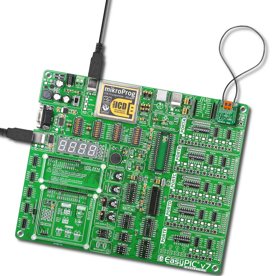
EasyPIC v7
Compiler
NECTO Studio
MCU
PIC18LF2455
Revolutionize applications across industries by harnessing conductive rubber cords to accurately measure and optimize stretch forces for enhanced design and performance
A
A
Hardware Overview
How does it work?
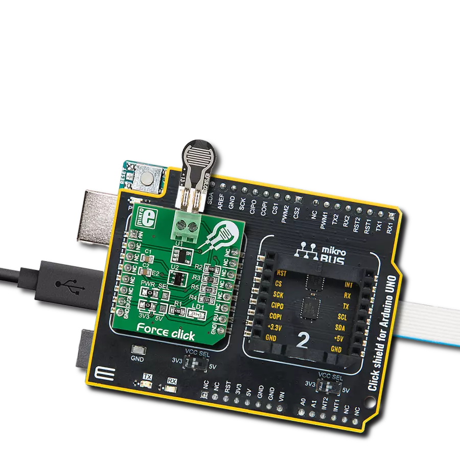
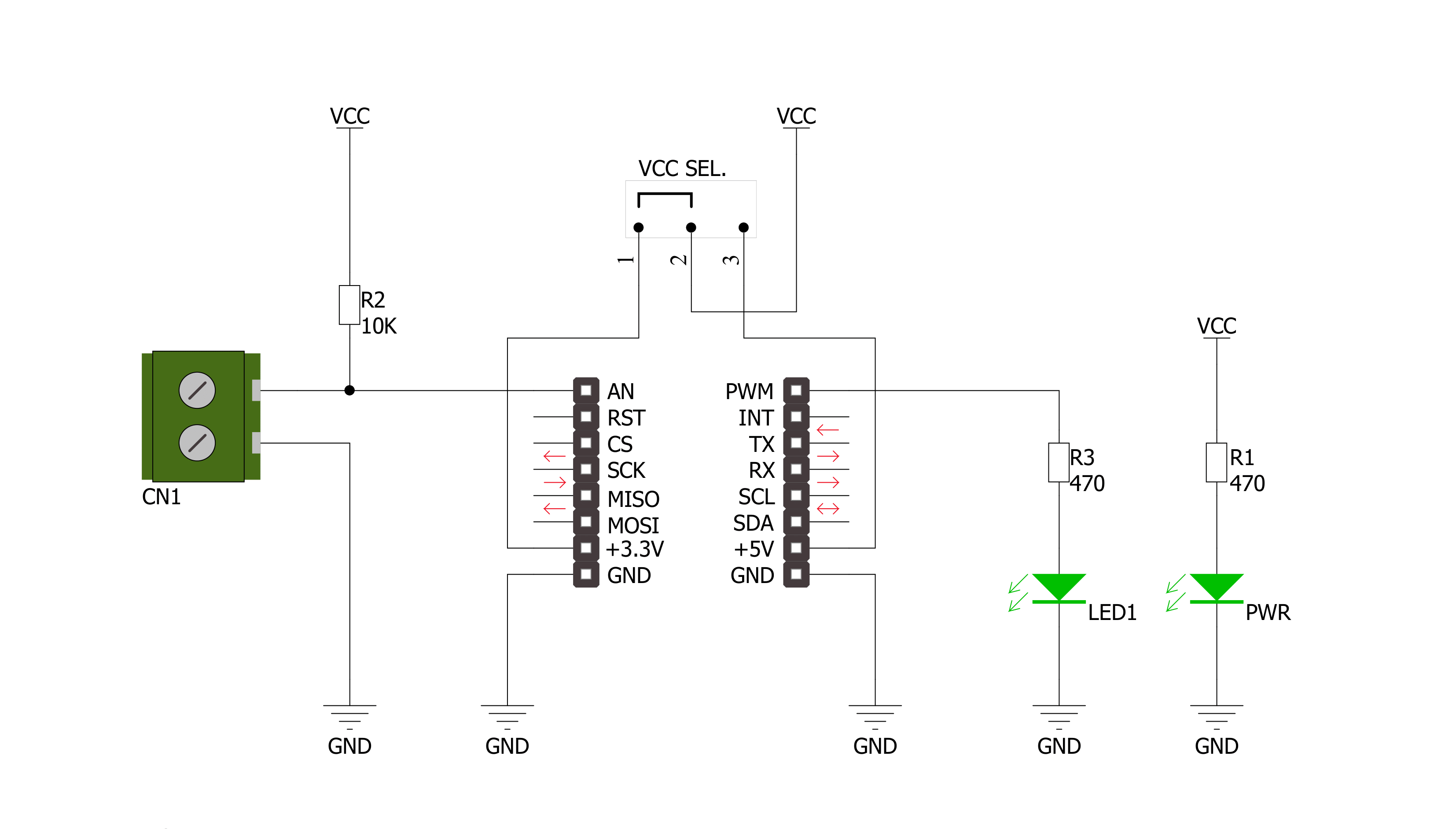
Stretch Click is based on the circuitry that allows measuring the stretch forces of the 2mm diameter conductive rubber cord. In a "relaxed" state, the resistance is about 130 ohms per centimeter. The resistance increases as you stretch it out (the particles get further apart); for example, a 15cm piece is proportional to 2.1k ohms (25cm long stretch is 26/15*2.1K = 3.5k ohms). You can stretch the rubber about 50-70% longer than the resting length, so a 15cm piece shouldn't be stretched more than 25cm. Once the force is released, the rubber will shrink back, although it's not very
"fast" and it takes a minute or two to revert to its original length. The resistance of the cord increases when stretched, impacting the reverse voltage on the voltage divider, which can be measured. The Stretch Click allows stretch force readings to be available on an analog AN pin of the mikroBUS™ socket. It's not a true linear sensor, and the resistance may vary from batch to batch, so we consider it a way to measure stretching motion, but it isn't really precise. In addition, this Click board™ features a user-configurable LED1 light-emitting diode that can
visually represent the measured force. This LED1 can be controlled over the PWM pin of the mikroBUS™ socket. This Click board™ can operate with either 3.3V or 5V logic voltage levels selected via the J1 SEL jumper. This way, both 3.3V and 5V capable MCUs can use the communication lines properly. Also, this Click board™ comes equipped with a library containing easy-to-use functions and an example code that can be used as a reference for further development.

Features overview
Development board
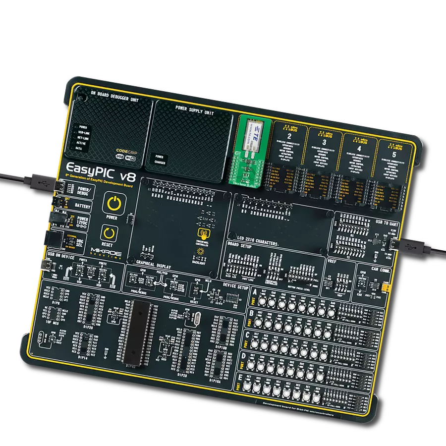
EasyPIC v7 is the seventh generation of PIC development boards specially designed to develop embedded applications rapidly. It supports a wide range of 8-bit PIC microcontrollers from Microchip and has a broad set of unique functions, such as a powerful onboard mikroProg programmer and In-Circuit debugger over USB-B. The development board is well organized and designed so that the end-user has all the necessary elements in one place, such as switches, buttons, indicators, connectors, and others. With four different connectors for each port, EasyPIC v7 allows you to connect accessory boards, sensors, and custom electronics more efficiently than ever. Each part of
the EasyPIC v7 development board contains the components necessary for the most efficient operation of the same board. An integrated mikroProg, a fast USB 2.0 programmer with mikroICD hardware In-Circuit Debugger, offers many valuable programming/debugging options and seamless integration with the Mikroe software environment. Besides it also includes a clean and regulated power supply block for the development board. It can use various external power sources, including an external 12V power supply, 7-23V AC or 9-32V DC via DC connector/screw terminals, and a power source via the USB Type-B (USB-B) connector. Communication options such as
USB-UART and RS-232 are also included, alongside the well-established mikroBUS™ standard, three display options (7-segment, graphical, and character-based LCD), and several different DIP sockets. These sockets cover a wide range of 8-bit PIC MCUs, from PIC10F, PIC12F, PIC16F, PIC16Enh, PIC18F, PIC18FJ, and PIC18FK families. EasyPIC v7 is an integral part of the Mikroe ecosystem for rapid development. Natively supported by Mikroe software tools, it covers many aspects of prototyping and development thanks to a considerable number of different Click boards™ (over a thousand boards), the number of which is growing every day.

Microcontroller Overview
MCU Card / MCU
Architecture
PIC
MCU Memory (KB)
24
Silicon Vendor
Microchip
Pin count
28
RAM (Bytes)
2048
Used MCU Pins
mikroBUS™ mapper
Take a closer look
Click board™ Schematic
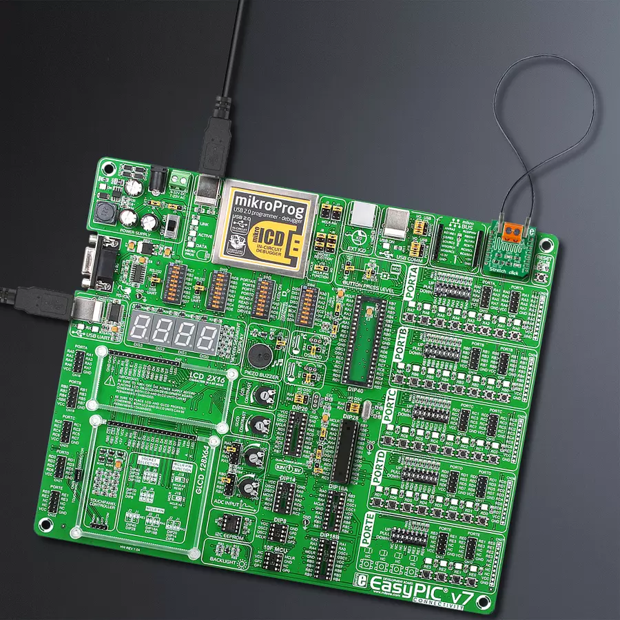
Step by step
Project assembly

Start by selecting your development board and Click board™. Begin with the EasyPIC v7 as your development board.


Track your results in real time
Application Output
1. Application Output - In Debug mode, the 'Application Output' window enables real-time data monitoring, offering direct insight into execution results. Ensure proper data display by configuring the environment correctly using the provided tutorial.

2. UART Terminal - Use the UART Terminal to monitor data transmission via a USB to UART converter, allowing direct communication between the Click board™ and your development system. Configure the baud rate and other serial settings according to your project's requirements to ensure proper functionality. For step-by-step setup instructions, refer to the provided tutorial.

3. Plot Output - The Plot feature offers a powerful way to visualize real-time sensor data, enabling trend analysis, debugging, and comparison of multiple data points. To set it up correctly, follow the provided tutorial, which includes a step-by-step example of using the Plot feature to display Click board™ readings. To use the Plot feature in your code, use the function: plot(*insert_graph_name*, variable_name);. This is a general format, and it is up to the user to replace 'insert_graph_name' with the actual graph name and 'variable_name' with the parameter to be displayed.

Software Support
Library Description
This library contains API for Stretch Click driver.
Key functions:
stretch_cfg_setup- Config Object Initialization functionstretch_turn_on_led- Turn on the LED functionstretch_turn_off_led-Turn off the LED function
Open Source
Code example
The complete application code and a ready-to-use project are available through the NECTO Studio Package Manager for direct installation in the NECTO Studio. The application code can also be found on the MIKROE GitHub account.
/*!
 * \file
 * \brief Stretch Click example
 *
 * # Description
 * The application is for stretch measuring
 *
 * The demo application is composed of two sections :
 *
 * ## Application Init
 * Initialization driver enables GPIO and ADC, turn off the LED and starts write log.
 *
 * ## Application Task
 * This is a example which demonstrates the use of Stretch Click board. Stretch Click reads and display ADC value.
 *
 * \author MikroE Team
 *
 */
// ------------------------------------------------------------------- INCLUDES

#include "board.h"
#include "log.h"
#include "stretch.h"

// ------------------------------------------------------------------ VARIABLES

static stretch_t stretch;
static log_t logger;

// ------------------------------------------------------- ADDITIONAL FUNCTIONS


// ------------------------------------------------------ APPLICATION FUNCTIONS

void application_init ( void )
{
    log_cfg_t log_cfg;
    stretch_cfg_t cfg;

    /**
     * Logger initialization.
     * Default baud rate: 115200
     * Default log level: LOG_LEVEL_DEBUG
     * @note If USB_UART_RX and USB_UART_TX
     * are defined as HAL_PIN_NC, you will
     * need to define them manually for log to work.
     * See @b LOG_MAP_USB_UART macro definition for detailed explanation.
     */
    LOG_MAP_USB_UART( log_cfg );
    log_init( &logger, &log_cfg );
    log_info( &logger, "---- Application Init ----" );

    //  Click initialization.

    stretch_cfg_setup( &cfg );
    STRETCH_MAP_MIKROBUS( cfg, MIKROBUS_1 );
    stretch_init( &stretch, &cfg );

    Delay_100ms();

    log_printf( &logger, "------------------- \r\n" );
    log_printf( &logger, "  Stretch  Click  "  );
    log_printf( &logger, "-------------------\r\n" );

    stretch_turn_off_led( &stretch );
    Delay_100ms( );

    log_printf( &logger, " ADC Initializated " );
    log_printf( &logger, "-------------------" );
}

void application_task ( void )
{
    stretch_data_t tmp;

    //  Task implementation.

    tmp = stretch_generic_read ( &stretch );
    log_printf( &logger, "** ADC value : [DEC]- %d, [HEX]- 0x%x \r\n", tmp, tmp );
    Delay_ms ( 1000 );

    Delay_100ms( );

    if ( tmp < 500 )
    {
        stretch_turn_on_led( &stretch );
    }

    else
    {
        stretch_turn_off_led( &stretch );
    }

    log_printf( &logger, " Resistance : %d \r\n", tmp );
    log_printf( &logger, "-------------------\r\n" );
    Delay_1sec( );
}

int main ( void )
{
    /* Do not remove this line or clock might not be set correctly. */
    #ifdef PREINIT_SUPPORTED
    preinit();
    #endif

    application_init( );

    for ( ; ; )
    {
        application_task( );
    }

    return 0;
}


// ------------------------------------------------------------------------ END