Achieve completely isolated bidirectional I2C communication with ADuM1252 and STM32F407VGT6
Reliable and high-speed data transfer with the added benefit of isolation

Published Dec 29, 2023
Click board™
I2C Isolator 7 Click
Dev. board
Clicker 4 for STM32F4
Compiler
NECTO Studio
MCU
STM32F407VGT6
Help devices from different "worlds" (with different power sources or electrical characteristics) to talk to each other safely and consistently
A
A
Hardware Overview
How does it work?
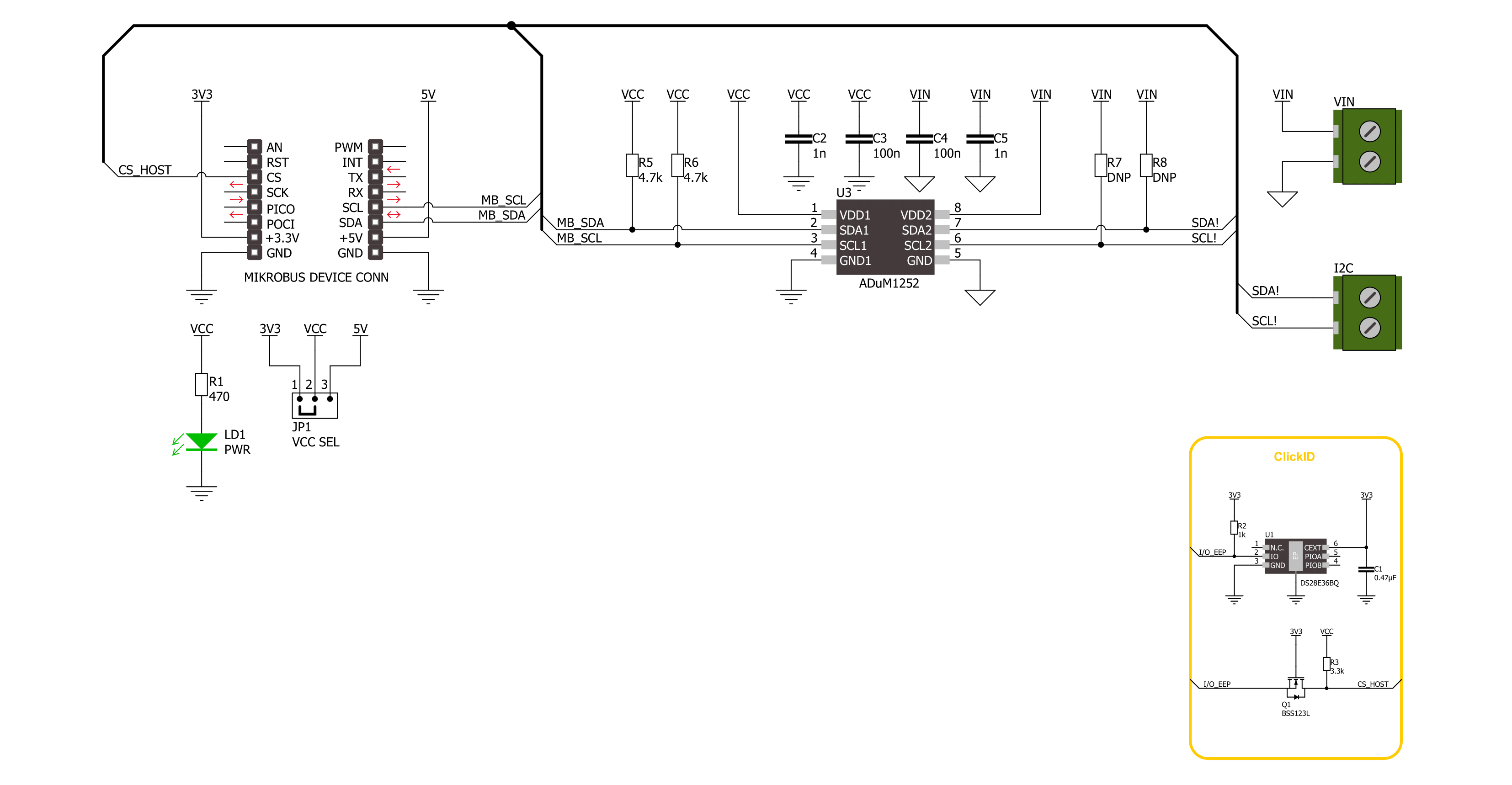
I2C Isolator 7 Click is based on the ADuM1252, an ultra-low power, bidirectional I2C isolator from Analog Devices. It features independent power supplies on both sides. Side 1 is reserved for 3.3V and 5V of mikroBUS™ socket rails, while side 2 can be supplied in a range of 1.71V up to 5.5V. To prevent latch-up action, its side 1 outputs comprise a special buffer that regulates the logic-low voltage, and the input logic-low threshold is
lower than the output logic-low voltage. In addition, side 2 features conventional buffers that do not regulate logic-low output voltage. I2C Isolator 7 Click uses a standard 2-Wire I2C interface to allow the host MCU to have an isolated bidirectional data transfer with a connected I2C device to the I2C terminals. As we mentioned, besides the I2C bus, the power supply is isolated, too. Places for optional pull-ups on the I2C bus are
left unpopulated. You can solder resistors according to your needs. This Click board™ can operate with either 3.3V or 5V logic voltage levels selected via the VCC SEL jumper. This way, both 3.3V and 5V capable MCUs can use the communication lines properly. Also, this Click board™ comes equipped with a library containing easy-to-use functions and an example code that can be used for further development.

Features overview
Development board
Clicker 4 for STM32F4 is a compact development board designed as a complete solution that you can use to quickly build your own gadgets with unique functionalities. Featuring an STM32F407VGT6 MCU, four mikroBUS™ sockets for Click boards™ connectivity, power management, and more, it represents a perfect solution for the rapid development of many different types of applications. At its core is an STM32F407VGT6 MCU, a powerful microcontroller by STMicroelectronics based on the high-performance
Arm® Cortex®-M4 32-bit processor core operating at up to 168 MHz frequency. It provides sufficient processing power for the most demanding tasks, allowing Clicker 4 to adapt to any specific application requirements. Besides two 1x20 pin headers, four improved mikroBUS™ sockets represent the most distinctive connectivity feature, allowing access to a huge base of Click boards™, growing on a daily basis. Each section of Clicker 4 is clearly marked, offering an intuitive and clean interface. This makes working with the
development board much simpler and, thus, faster. The usability of Clicker 4 doesn’t end with its ability to accelerate the prototyping and application development stages: it is designed as a complete solution that can be implemented directly into any project, with no additional hardware modifications required. Four mounting holes [4.2mm/0.165”] at all four corners allow simple installation by using mounting screws.

Microcontroller Overview
MCU Card / MCU

Architecture
ARM Cortex-M4
MCU Memory (KB)
10
Silicon Vendor
STMicroelectronics
Pin count
100
RAM (Bytes)
100
Used MCU Pins
mikroBUS™ mapper
Take a closer look
Click board™ Schematic
Step by step
Project assembly

Start by selecting your development board and Click board™. Begin with the Clicker 4 for STM32F4 as your development board.


Software Support
Library Description
This library contains API for I2C Isolator 7 Click driver.
Key functions:
i2cisolator7_generic_write- This function shall generate a START signal, followed by len number of writes from data_in.i2cisolator7_generic_read- This function shall generate a START signal, followed by len number of reads from the bus placing the data in data_out.i2cisolator7_write_then_read- This function performs a write operation followed by a read operation on the bus by using I2C serial interface.
Open Source
Code example
The complete application code and a ready-to-use project are available through the NECTO Studio Package Manager for direct installation in the NECTO Studio. The application code can also be found on the MIKROE GitHub account.
/*!
* @file main.c
* @brief I2C Isolator 7 Click example
*
* # Description
* This demo application shows an example of an I2C Isolator 7 Click
* wired to the PRESS Click board™ for reading device ID (Who am I).
* The library also includes an I2C writing and reading functions.
*
* The demo application is composed of two sections :
*
* ## Application Init
* The initialization of I2C module and log UART.
* After driver initialization, the app sets the PRESS Click board™ slave address.
*
* ## Application Task
* This example demonstrates the use of the I2C Isolator 7 Click board™.
* Logs device ID values of the PRESS Click board™
* wired to the I2C Isolator 7 Click board™.
*
*
* @author Nenad Filipovic
*
*/
#include "board.h"
#include "log.h"
#include "i2cisolator7.h"
#define PRESS_DEVICE_ADDRESS 0x5C
#define PRESS_REG_WHO_AM_I 0x0F
#define PRESS_WHO_AM_I 0xB4
static i2cisolator7_t i2cisolator7;
static log_t logger;
void application_init ( void )
{
log_cfg_t log_cfg; /**< Logger config object. */
i2cisolator7_cfg_t i2cisolator7_cfg; /**< Click config object. */
/**
* Logger initialization.
* Default baud rate: 115200
* Default log level: LOG_LEVEL_DEBUG
* @note If USB_UART_RX and USB_UART_TX
* are defined as HAL_PIN_NC, you will
* need to define them manually for log to work.
* See @b LOG_MAP_USB_UART macro definition for detailed explanation.
*/
LOG_MAP_USB_UART( log_cfg );
log_init( &logger, &log_cfg );
log_info( &logger, " Application Init " );
// Click initialization.
i2cisolator7_cfg_setup( &i2cisolator7_cfg );
I2CISOLATOR7_MAP_MIKROBUS( i2cisolator7_cfg, MIKROBUS_1 );
if ( I2C_MASTER_ERROR == i2cisolator7_init( &i2cisolator7, &i2cisolator7_cfg ) )
{
log_error( &logger, " Communication init." );
for ( ; ; );
}
Delay_ms ( 100 );
if ( I2CISOLATOR7_ERROR == i2cisolator7_set_slave_address( &i2cisolator7, PRESS_DEVICE_ADDRESS ) )
{
log_error( &logger, " Set I2C Slave address ERROR." );
for ( ; ; );
}
Delay_ms ( 100 );
log_info( &logger, " Application Task " );
log_printf( &logger, "---------------------\r\n" );
Delay_ms ( 100 );
}
void application_task ( void )
{
uint8_t device_id = 0;
uint8_t reg = PRESS_REG_WHO_AM_I;
if ( I2CISOLATOR7_OK == i2cisolator7_write_then_read( &i2cisolator7, ®, 1, &device_id, 1 ) )
{
if ( PRESS_WHO_AM_I == device_id )
{
log_printf( &logger, " Device ID: 0x%.2X\r\n", ( uint16_t ) device_id );
log_printf( &logger, "---------------------\r\n" );
}
}
Delay_ms ( 1000 );
}
int main ( void )
{
/* Do not remove this line or clock might not be set correctly. */
#ifdef PREINIT_SUPPORTED
preinit();
#endif
application_init( );
for ( ; ; )
{
application_task( );
}
return 0;
}
// ------------------------------------------------------------------------ END
Additional Support
Resources
Category:I2C


