Unlock the potential of extended I2C communication with LTC4331 and PIC32MZ2048EFM100
Reliable I2C over long distances

Published Sep 12, 2023
Click board™
I2C Extend Click
Dev. board
Curiosity PIC32 MZ EF
Compiler
NECTO Studio
MCU
PIC32MZ2048EFM100
Achieve reliable I2C communication over long distances, ensuring your data reaches its destination intact and on time
A
A
Hardware Overview
How does it work?
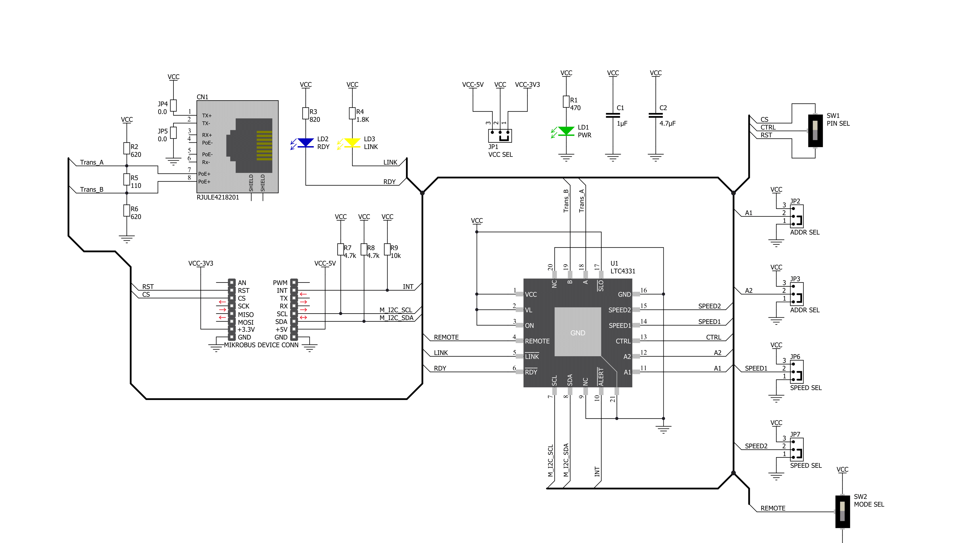
I2C Extend Click is based on the LTC4331, a point-to-point compatible I2C peripheral device extender designed for operation in high-noise industrial environments. Using a ±60V fault-protected differential transceiver, the LTC4331 can extend an I2C/SMBus bus, including a remote interrupt function and a control signal, over a single twisted pair differential link. Thanks to selectable link baud rates, the I2C bus can be extended up to 1200m, depending on the link speed and external factors such as environmental noise level, humidity, cable quality, and more. Standard twisted-pair cables with RJ45 connectors can be used, the same as in the ethernet devices, and more. Besides the I2C protocol extension, the I2C Extend click also supports local remote control and interrupt functions. Local to remote control ensures that the values set on the local side CTRL pin propagate to the remote side CTRL pin over
the differential link. Users can choose a pin on the mikroBUS™ socket used for that purpose (CS or RST) using the onboard jumper named PIN SEL. The interrupt pin acts as an open-drain output in local mode and an input in remote mode. An interrupt signal on the INT pin in the I2C Extend Click is mirrored from the remote to the local network using the differential link. On the remote side, INT is an input pin that can be connected to remote I2C peripheral devices, while on the local side, it operates as an open-drain output that can be connected to a shared local interrupt line. Because of the dual functionality of the I2C Extend Click, the user needs to set the mode of operation of the Click board™. That is easily achieved using the onboard MODE switch, with two positions: local mode (LCL), where this Click board™ is in I2C slave mode, and remote mode (RMT), where this Click board™ is in I2C master mode. Besides mode
selection, I2C Extend Click can also link speed and I2C address selection jumpers onboard, named SPEED SEL and ADDR SEL, respectively. This Click board™ has Link status (LINK) and ready status (RDY) LEDs, making troubleshooting easy. The LINK LED activates in remote mode when the device establishes link communication. In local mode, the LINK LED is active after the LTC4331’s I2C interface has joined the I2C bus and establishes link communication. The RDY LED is active after the device’s I2C interface has joined the bus. This Click board™ can operate with either 3.3V or 5V logic voltage levels selected via the VCC SEL jumper. This way, both 3.3V and 5V capable MCUs can use the communication lines properly. Also, this Click board™ comes equipped with a library containing easy-to-use functions and an example code that can be used as a reference for further development.

Features overview
Development board
Curiosity PIC32 MZ EF development board is a fully integrated 32-bit development platform featuring the high-performance PIC32MZ EF Series (PIC32MZ2048EFM) that has a 2MB Flash, 512KB RAM, integrated FPU, Crypto accelerator, and excellent connectivity options. It includes an integrated programmer and debugger, requiring no additional hardware. Users can expand
functionality through MIKROE mikroBUS™ Click™ adapter boards, add Ethernet connectivity with the Microchip PHY daughter board, add WiFi connectivity capability using the Microchip expansions boards, and add audio input and output capability with Microchip audio daughter boards. These boards are fully integrated into PIC32’s powerful software framework, MPLAB Harmony,
which provides a flexible and modular interface to application development a rich set of inter-operable software stacks (TCP-IP, USB), and easy-to-use features. The Curiosity PIC32 MZ EF development board offers expansion capabilities making it an excellent choice for a rapid prototyping board in Connectivity, IOT, and general-purpose applications.

Microcontroller Overview
MCU Card / MCU

Architecture
PIC32
MCU Memory (KB)
2048
Silicon Vendor
Microchip
Pin count
100
RAM (Bytes)
524288
Used MCU Pins
mikroBUS™ mapper
Take a closer look
Click board™ Schematic
Step by step
Project assembly

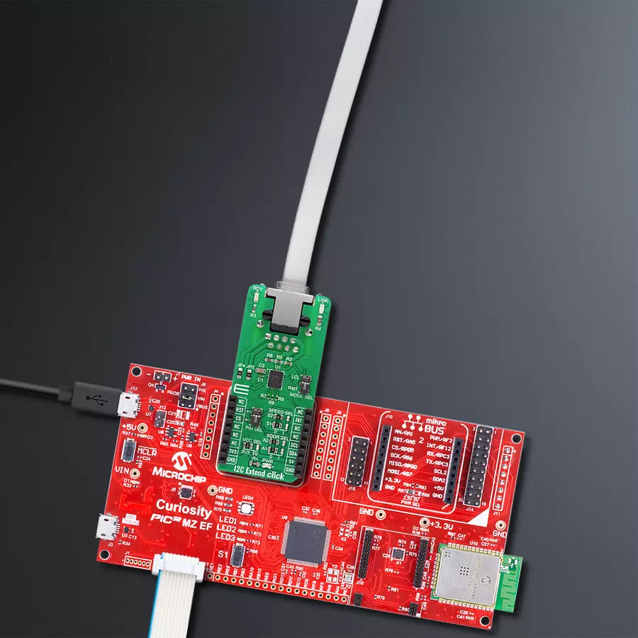
Start by selecting your development board and Click board™. Begin with the Curiosity PIC32 MZ EF as your development board.


Software Support
Library Description
This library contains API for I2C Extend Click driver.
Key functions:
i2cextend_rmt_multi_read- Generic multi read data in Remote Mode functioni2cextend_set_config- Set the configuration functioni2cextend_set_out_slave_address- Set out slave address function.
Open Source
Code example
The complete application code and a ready-to-use project are available through the NECTO Studio Package Manager for direct installation in the NECTO Studio. The application code can also be found on the MIKROE GitHub account.
/*!
 * @file main.c
 * @brief I2CExtend Click example
 *
 * # Description
 * This is an example which demonstrates the use of I2C Extend Click board.
 *
 * The demo application is composed of two sections :
 *
 * ## Application Init
 * Initialization driver enables - I2C,
 * check communication with device 6DOF IMU 11 Click
 * connected to the I2C Extend Click ( Remote Mode ),
 * set default configuration and start measurement.
 *
 * ## Application Task
 * In this example, we read Accel and Mag axis of the connected
 * 6DOF IMU 11 Click boards to the I2C Extend Click ( Remote Mode )
 * which is connected by a LAN cable to I2C Extend Click ( Local Mode ).
 * Results are being sent to the Usart Terminal where you can track their changes.
 * All data logs write on USB uart changes for every 2 sec.
 *
 * @author Stefan Ilic
 *
 */

#include "board.h"
#include "log.h"
#include "i2cextend.h"

static i2cextend_t i2cextend;
static log_t logger;
int16_t axis;

void i2cextend_6dofimu11_get_axis ( i2cextend_t *ctx, uint8_t axis_out_reg ) {
    uint16_t rx_val;
    uint8_t rx_buf[ 2 ];

    i2cextend_rmt_multi_read( ctx, C6DOFIMU11_I2C_SLAVE_ADDRESS_GND, axis_out_reg, &rx_buf[ 0 ], 2 );

    rx_val = rx_buf[ 1 ];
    rx_val <<= 8;
    rx_val |= rx_buf[ 0 ];

    axis = ( int16_t ) rx_val;
}

void application_init ( void ) {
    log_cfg_t log_cfg;  /**< Logger config object. */
    i2cextend_cfg_t i2cextend_cfg;  /**< Click config object. */

    /**
     * Logger initialization.
     * Default baud rate: 115200
     * Default log level: LOG_LEVEL_DEBUG
     * @note If USB_UART_RX and USB_UART_TX
     * are defined as HAL_PIN_NC, you will
     * need to define them manually for log to work.
     * See @b LOG_MAP_USB_UART macro definition for detailed explanation.
     */
    LOG_MAP_USB_UART( log_cfg );
    log_init( &logger, &log_cfg );
    log_info( &logger, " Application Init " );

    // Click initialization.
    i2cextend_cfg_setup( &i2cextend_cfg );
    I2CEXTEND_MAP_MIKROBUS( i2cextend_cfg, MIKROBUS_1 );
    err_t init_flag = i2cextend_init( &i2cextend, &i2cextend_cfg );
    if ( I2C_MASTER_ERROR == init_flag ) {
        log_error( &logger, " Application Init Error. " );
        log_info( &logger, " Please, run program again... " );

        for ( ; ; );
    }

    if ( i2cextend_rmt_read( &i2cextend, C6DOFIMU11_I2C_SLAVE_ADDRESS_GND, C6DOFIMU11_REG_WHO_AM_I ) == C6DOFIMU11_WHO_AM_I_WIA_ID ) {
        log_printf( &logger, "        SUCCESS         \r\n" );
        log_printf( &logger, "------------------------\r\n" );
    } else {
        log_printf( &logger, "         ERROR          \r\n" );
        log_printf( &logger, "    Reset the device    \r\n" );
        log_printf( &logger, "------------------------\r\n" );
        for ( ; ; );
    }
    i2cextend_rmt_write( &i2cextend, C6DOFIMU11_I2C_SLAVE_ADDRESS_GND, C6DOFIMU11_REG_CNTL2, C6DOFIMU11_CNTL2_TEMP_EN_STANDBY_MODE |
                                                                                  C6DOFIMU11_CNTL2_MAG_EN_STANDBY_MODE |
                                                                                  C6DOFIMU11_CNTL2_ACCEL_EN_STANDBY_MODE );

    i2cextend_rmt_write ( &i2cextend, C6DOFIMU11_I2C_SLAVE_ADDRESS_GND, C6DOFIMU11_REG_INC3, C6DOFIMU11_INC3_IEL2_FIFO_TRIG |
                                                                                  C6DOFIMU11_INC3_IEL1_FIFO_TRIG );

    i2cextend_rmt_write ( &i2cextend, C6DOFIMU11_I2C_SLAVE_ADDRESS_GND, C6DOFIMU11_REG_CNTL2, C6DOFIMU11_CNTL2_GSEL_8G |
                                                                                   C6DOFIMU11_CNTL2_RES_MAX2 |
                                                                                   C6DOFIMU11_CNTL2_MAG_EN_OPERATING_MODE |
                                                                                   C6DOFIMU11_CNTL2_ACCEL_EN_OPERATING_MODE );
    log_info( &logger, " Application Task " );
    log_printf( &logger, "------------------------\r\n" );
}

void application_task ( void ) {
    log_printf( &logger, "\t   Accel   \t|\t    Mag    \r\n" );
    log_printf( &logger, "------------------------------------------------\r\n" );

    i2cextend_6dofimu11_get_axis( &i2cextend, C6DOFIMU11_REG_ACCEL_XOUT_L );
    log_printf( &logger, "\t Accel X: %d\t|", axis );
    i2cextend_6dofimu11_get_axis( &i2cextend, C6DOFIMU11_REG_MAG_XOUT_L );
    log_printf( &logger, "\t Mag X: %d\r\n", axis );

    i2cextend_6dofimu11_get_axis( &i2cextend, C6DOFIMU11_REG_ACCEL_YOUT_L );
    log_printf( &logger, "\t Accel Y: %d\t|", axis );
    i2cextend_6dofimu11_get_axis( &i2cextend, C6DOFIMU11_REG_MAG_YOUT_L );
    log_printf( &logger, "\t Mag Y: %d\r\n", axis );

    i2cextend_6dofimu11_get_axis( &i2cextend, C6DOFIMU11_REG_ACCEL_ZOUT_L );
    log_printf( &logger, "\t Accel Z: %d\t|", axis );
    i2cextend_6dofimu11_get_axis( &i2cextend, C6DOFIMU11_REG_MAG_ZOUT_L );
    log_printf( &logger, "\t Mag Z: %d\r\n", axis );

    log_printf( &logger, "------------------------------------------------\r\n" );
    Delay_ms ( 1000 );
}

int main ( void )
{
    /* Do not remove this line or clock might not be set correctly. */
    #ifdef PREINIT_SUPPORTED
    preinit();
    #endif

    application_init( );

    for ( ; ; )
    {
        application_task( );
    }

    return 0;
}

// ------------------------------------------------------------------------ END
Additional Support
Resources
Category:I2C


