Adjust and optimize critical settings in your projects with 67WR100KLF and STM32F407VGT6
Trim with precision: Elevate control with our trimmer potentiometer

Published Dec 29, 2023
Click board™
POT 2 Click
Dev. board
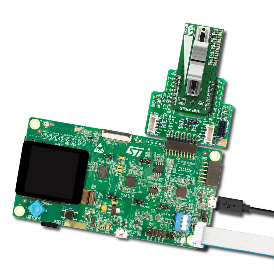
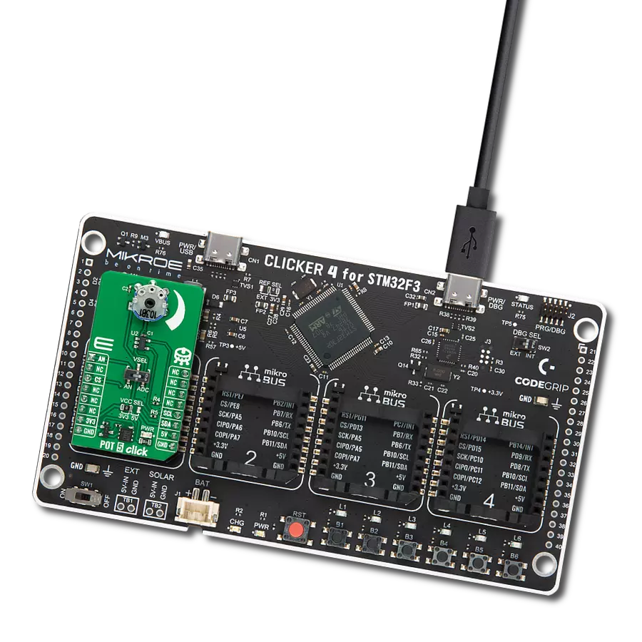
Clicker 4 for STM32F4
Compiler
NECTO Studio
MCU
STM32F407VGT6
Our trimmer potentiometers are meticulously crafted to deliver unparalleled precision, enabling you to calibrate and fine-tune your equipment with exceptional accuracy, so you can achieve peak performance effortlessly
A
A
Hardware Overview
How does it work?
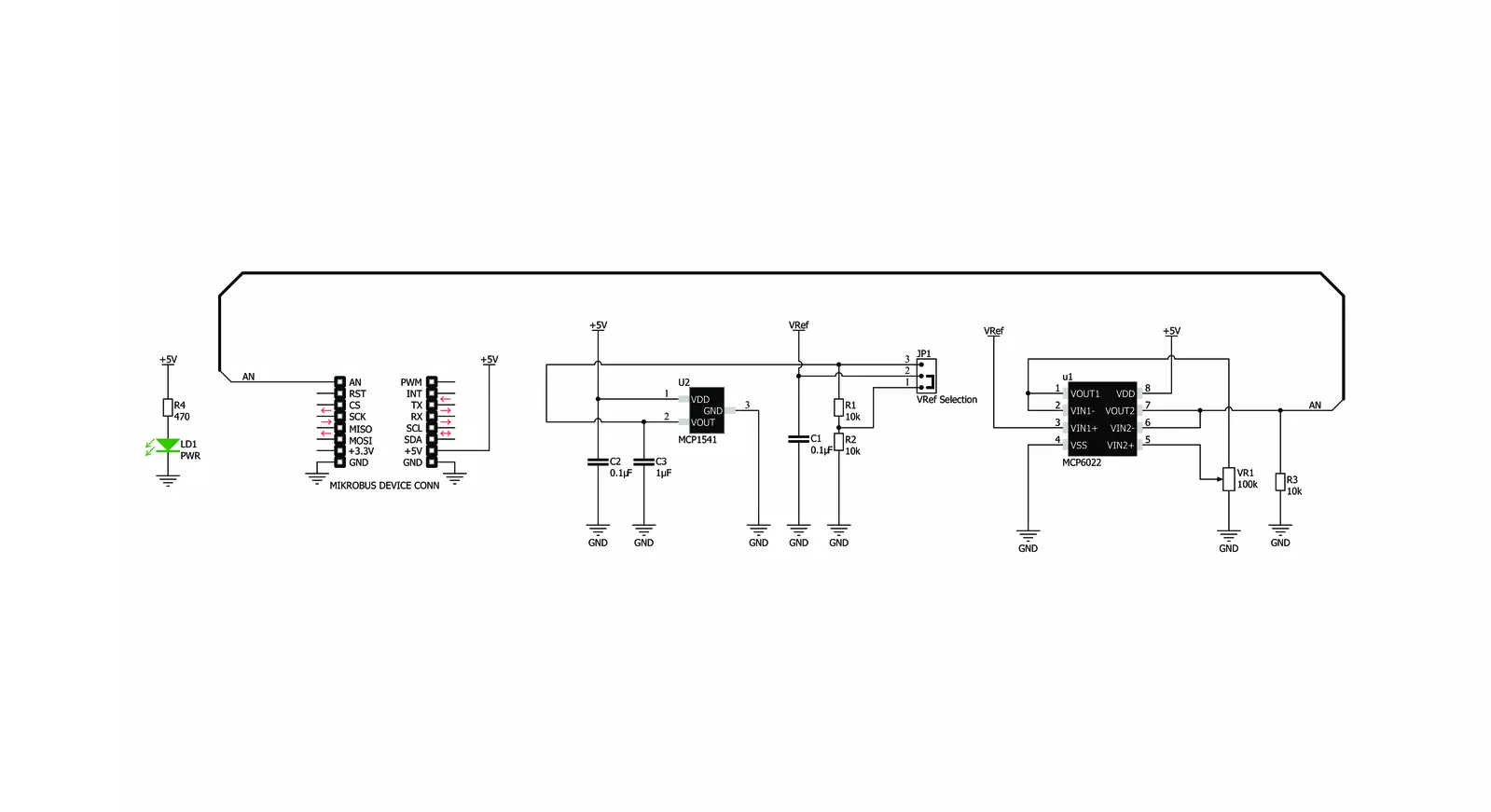
POT 2 Click is based on the MCP1541, a precision voltage reference IC from Microchip is used to provide the voltage of 4.096V. is fed to an input of an operational amplifier, that acts as the buffer, with the unity gain. The output of the first buffer is fed to one end of a high-precision trimmer-potentiometer. The second end of the potentiometer is grounded, while the middle tap of the potentiometer is used as the input to a second buffer. The output of the second buffer is routed to the AN pin of the mikroBUS™, allowing the host microcontroller (MCU) to use the output voltage for any purpose. The design uses the MCP6022, a dual, rail-to-rail operational amplifier from Microchip. This operational amplifier is a perfect choice for this design, as it allows rail-to-rail
operation, uses a single power supply of 5V, and has a stable unity gain. Without the buffers, the variable impedance would affect the reference voltage. The reference voltage IC can provide less than 10 mA, with the significant voltage drop for output currents exceeding 2 mA. Therefore, the MCP6022 used as a dual buffer ensures good stability of the circuit. The potentiometer itself is a multi-turn type of potentiometer which provides high accuracy. It is equipped with a screw, which can be rotated 20 times between the end positions. This allows the resistance to be precisely selected. The fact that the screw fits tightly into the casing of the potentiometer, ensures that no resistance variations are possible, unlike the conventional knob or slider potentiometers.
POT 2 click is equipped with the SMD jumper, which is used to select the voltage reference for the potentiometer. There are two options available: 2.048V and 4.096V. These values are the most commonly used voltage references for different kinds of A/D converters. Most MCUs which use 3.3V for the power supply, do not have the option to use 4.096V (full voltage output of the MCP1541 IC), so an option to select 2.048V by dividing the output voltage of the MCP1541 IC, is very useful in that case. The voltage reference can be selected by moving the SMD jumper labeled as VRef SEL to the desired position (2.048V or 4.096V).


Features overview
Development board
Clicker 4 for STM32F4 is a compact development board designed as a complete solution that you can use to quickly build your own gadgets with unique functionalities. Featuring an STM32F407VGT6 MCU, four mikroBUS™ sockets for Click boards™ connectivity, power management, and more, it represents a perfect solution for the rapid development of many different types of applications. At its core is an STM32F407VGT6 MCU, a powerful microcontroller by STMicroelectronics based on the high-performance
Arm® Cortex®-M4 32-bit processor core operating at up to 168 MHz frequency. It provides sufficient processing power for the most demanding tasks, allowing Clicker 4 to adapt to any specific application requirements. Besides two 1x20 pin headers, four improved mikroBUS™ sockets represent the most distinctive connectivity feature, allowing access to a huge base of Click boards™, growing on a daily basis. Each section of Clicker 4 is clearly marked, offering an intuitive and clean interface. This makes working with the
development board much simpler and, thus, faster. The usability of Clicker 4 doesn’t end with its ability to accelerate the prototyping and application development stages: it is designed as a complete solution that can be implemented directly into any project, with no additional hardware modifications required. Four mounting holes [4.2mm/0.165”] at all four corners allow simple installation by using mounting screws.

Microcontroller Overview
MCU Card / MCU

Architecture
ARM Cortex-M4
MCU Memory (KB)
10
Silicon Vendor
STMicroelectronics
Pin count
100
RAM (Bytes)
100
Used MCU Pins
mikroBUS™ mapper
Take a closer look
Click board™ Schematic
Step by step
Project assembly

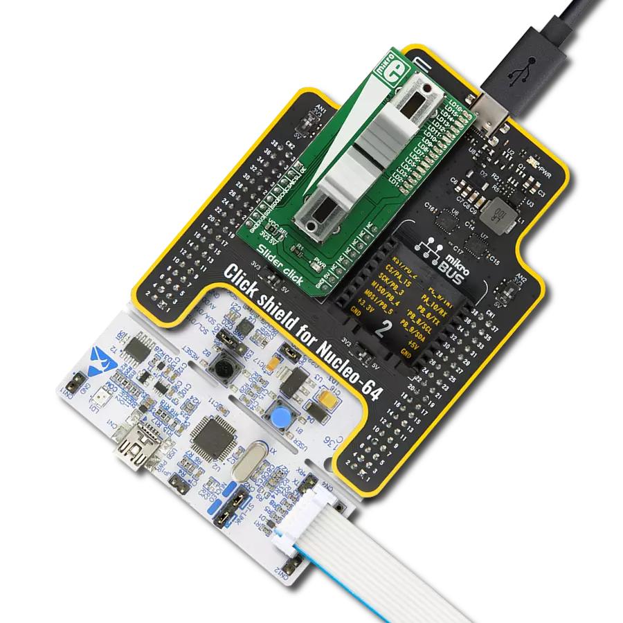
Start by selecting your development board and Click board™. Begin with the Clicker 4 for STM32F4 as your development board.


Track your results in real time
Application Output
1. Application Output - In Debug mode, the 'Application Output' window enables real-time data monitoring, offering direct insight into execution results. Ensure proper data display by configuring the environment correctly using the provided tutorial.

2. UART Terminal - Use the UART Terminal to monitor data transmission via a USB to UART converter, allowing direct communication between the Click board™ and your development system. Configure the baud rate and other serial settings according to your project's requirements to ensure proper functionality. For step-by-step setup instructions, refer to the provided tutorial.

3. Plot Output - The Plot feature offers a powerful way to visualize real-time sensor data, enabling trend analysis, debugging, and comparison of multiple data points. To set it up correctly, follow the provided tutorial, which includes a step-by-step example of using the Plot feature to display Click board™ readings. To use the Plot feature in your code, use the function: plot(*insert_graph_name*, variable_name);. This is a general format, and it is up to the user to replace 'insert_graph_name' with the actual graph name and 'variable_name' with the parameter to be displayed.

Software Support
Library Description
This library contains API for POT 2 Click driver.
Key functions:
pot2_generic_read- Generic read function
Open Source
Code example
The complete application code and a ready-to-use project are available through the NECTO Studio Package Manager for direct installation in the NECTO Studio. The application code can also be found on the MIKROE GitHub account.
/*!
 * \file
 * \brief Pot2 Click example
 *
 * # Description
 * This demo-app shows the ADC values using POT 2 Click board.
 *
 * The demo application is composed of two sections :
 *
 * ## Application Init
 * Configures Clicks and log objects.
 *
 * ## Application Task
 * Demo app reads ADC data and displays them as dec and hex values every second
 *
 * \author Jovan Stajkovic
 *
 */
// ------------------------------------------------------------------- INCLUDES

#include "board.h"
#include "log.h"
#include "pot2.h"

// ------------------------------------------------------------------ VARIABLES

static pot2_t pot2;
static log_t logger;

static uint16_t adc_val;
static float voltage_val;

// ------------------------------------------------------ APPLICATION FUNCTIONS

void application_init ( void )
{
    log_cfg_t log_cfg;
    pot2_cfg_t cfg;

    /**
     * Logger initialization.
     * Default baud rate: 115200
     * Default log level: LOG_LEVEL_DEBUG
     * @note If USB_UART_RX and USB_UART_TX
     * are defined as HAL_PIN_NC, you will
     * need to define them manually for log to work.
     * See @b LOG_MAP_USB_UART macro definition for detailed explanation.
     */
    LOG_MAP_USB_UART( log_cfg );
    log_init( &logger, &log_cfg );
    log_info( &logger, "---- Application Init ----" );

    //  Click initialization.

    pot2_cfg_setup( &cfg );
    POT2_MAP_MIKROBUS( cfg, MIKROBUS_1 );
    if ( pot2_init( &pot2, &cfg ) == ADC_ERROR )
    {
        log_info( &logger, "---- Application Init Error ----" );
        log_info( &logger, "---- Please, run program again ----" );

        for ( ; ; );
    }
    log_info( &logger, "---- Application Init Done ----\r\n" );

    voltage_val = 0;
    adc_val = 0;
}

void application_task ( void )
{
    if ( pot2_read_adc ( &pot2, &adc_val ) != ADC_ERROR )
    {
        log_printf( &logger, " ADC value : [DEC] %u, [HEX] 0x%x\r\n", adc_val, adc_val );
    }

    if ( pot2_read_pin_voltage ( &pot2, &voltage_val ) != ADC_ERROR )
    {
        log_printf( &logger, " Voltage value : %.2f\r\n", voltage_val );
    }

    log_printf( &logger, "------------------------------------------\r\n" );
    Delay_ms ( 1000 );
}

int main ( void )
{
    /* Do not remove this line or clock might not be set correctly. */
    #ifdef PREINIT_SUPPORTED
    preinit();
    #endif

    application_init( );

    for ( ; ; )
    {
        application_task( );
    }

    return 0;
}


// ------------------------------------------------------------------------ END
Additional Support
Resources
Category:Potentiometers