Achieve galvanic isolation of the SPI interface with MAX22345 and PIC18F97J94
Completely isolated SPI interface

Published Feb 12, 2024
Click board™
SPI Isolator 6 Click
Dev. board
CLICKER 4 for PIC18F
Compiler
NECTO Studio
MCU
PIC18F97J94
Create a communication bridge between devices with different power domains
A
A
Hardware Overview
How does it work?
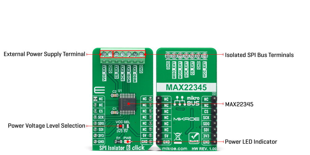
SPI Isolator 6 Click is based on the MAX22345, a four-channel digital isolator with a maximum data rate of 200Mbps from Analog Devices. The MAX22345 provides galvanic isolation for digital signals transmitted between two ground domains and can withstand up to 784Vpeak of continuous isolation and up to 3.75kVRMS for up to 60 seconds. Besides, Analog's proprietary process technology offers the low-power operation, high electromagnetic interference (EMI) immunity, and stable temperature performance.
Both power pins' wide supply voltage range allows the MAX22345 to be used for level translation and isolation. Because this Click board™ represents an isolator for SPI communication, it logically communicates with the MCU precisely through that communication. As already mentioned, the MAX22345 has two power pins for the A and B isolation sides, where it is possible to supply its B side with external voltage in the range of 1.7 to 5.5V by applying it to the terminal marked with VCC_EXT. In addition to the external power supply terminal,
this Click board™ also possesses another two terminals to which the isolated SPI data communication lines are routed. This Click board™ can operate with either 3.3V or 5V logic voltage levels selected via the VCC SEL jumper. This way, both 3.3V and 5V capable MCUs can use the communication lines properly. However, the Click board™ comes equipped with a library containing easy-to-use functions and an example code that can be used for further development.
Features overview
Development board
Clicker 4 for PIC18F is a compact development board designed as a complete solution to build your own gadgets with unique functionalities quickly. It features a PIC18F97J94MCU, four mikroBUS™ sockets for Click boards™ connectivity, power management, and more, and it is a perfect solution for the rapid development of many different types of applications. At its core is an 8-bit PIC18F97J94 MCU, a powerful microcontroller produced by Microchip, based on the high-performance CPU with two external clock modes, up to 64MHz. It
provides sufficient processing power for the most demanding tasks, allowing Clicker 4 to adapt to any specific application requirements. Besides two 1x20 pin headers, four improved mikroBUS™ sockets represent the most distinctive connectivity feature, allowing access to a huge base of Click boards™, growing on a daily basis. Each section of Clicker 4 is clearly marked, offering an intuitive and clean interface. This makes working with the development board much simpler and, thus, faster. The usability of Clicker 4 doesn’t end with its ability
to accelerate the prototyping and application development stages: it is designed as a complete solution that can be implemented directly into any project, with no additional hardware modifications required. Four mounting holes [4.2mm/0.165”] at all four corners allow simple installation by using mounting screws. For most applications, a nice, stylish casing is all that is needed to turn the Clicker 4 development board into a fully functional, custom design.

Microcontroller Overview
MCU Card / MCU
Architecture
PIC
MCU Memory (KB)
128
Silicon Vendor
Microchip
Pin count
100
RAM (Bytes)
3862
Used MCU Pins
mikroBUS™ mapper
Take a closer look
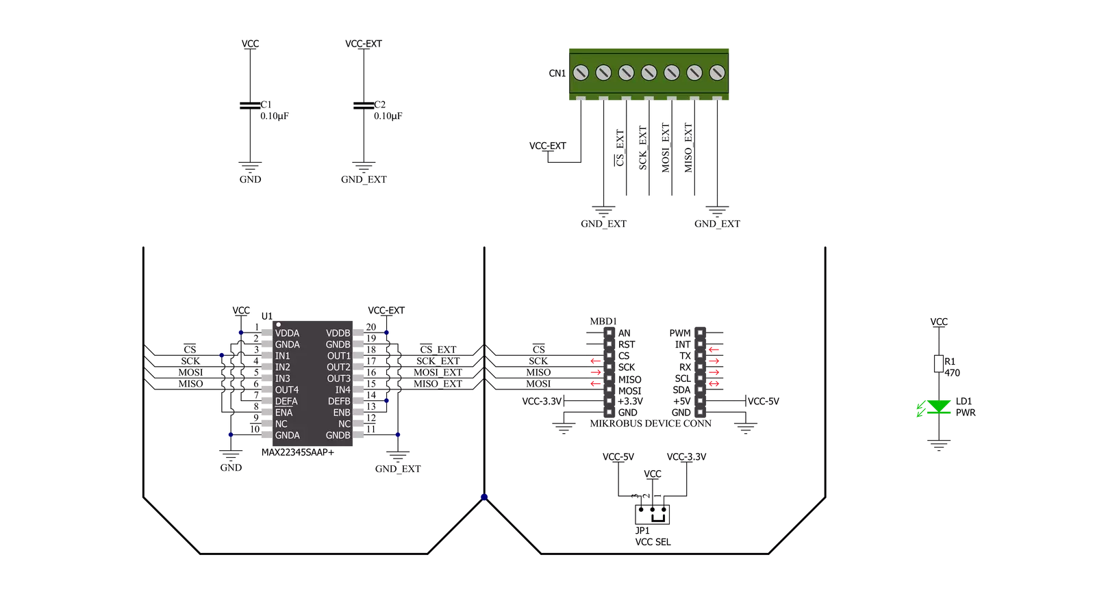
Click board™ Schematic
Step by step
Project assembly

Start by selecting your development board and Click board™. Begin with the CLICKER 4 for PIC18F as your development board.


Track your results in real time
Application Output
1. Application Output - In Debug mode, the 'Application Output' window enables real-time data monitoring, offering direct insight into execution results. Ensure proper data display by configuring the environment correctly using the provided tutorial.

2. UART Terminal - Use the UART Terminal to monitor data transmission via a USB to UART converter, allowing direct communication between the Click board™ and your development system. Configure the baud rate and other serial settings according to your project's requirements to ensure proper functionality. For step-by-step setup instructions, refer to the provided tutorial.

3. Plot Output - The Plot feature offers a powerful way to visualize real-time sensor data, enabling trend analysis, debugging, and comparison of multiple data points. To set it up correctly, follow the provided tutorial, which includes a step-by-step example of using the Plot feature to display Click board™ readings. To use the Plot feature in your code, use the function: plot(*insert_graph_name*, variable_name);. This is a general format, and it is up to the user to replace 'insert_graph_name' with the actual graph name and 'variable_name' with the parameter to be displayed.

Software Support
Library Description
This library contains API for SPI Isolator 6 Click driver.
Key functions:
spiisolator6_generic_writeThis function writes a desired number of data bytes by using SPI serial interface.spiisolator6_generic_readThis function writes and then reads a desired number of data bytes by using SPI serial interface.
Open Source
Code example
The complete application code and a ready-to-use project are available through the NECTO Studio Package Manager for direct installation in the NECTO Studio. The application code can also be found on the MIKROE GitHub account.
/*!
 * @file main.c
 * @brief SPIIsolator6 Click example
 *
 * # Description
 * This example demonstrates the use of SPI Isolator 6 Click board by reading the
 * device ID of the connected Accel 22 Click board.
 *
 * The demo application is composed of two sections :
 *
 * ## Application Init
 * Initializes the driver and logger.
 *
 * ## Application Task
 * Reads and checks the device ID of the connected Accel 22 Click board, and displays the
 * results on the USB UART approximately once per second.
 *
 * @note
 * Make sure to provide VCC power supply on VCC-EXT pin.
 *
 * @author Stefan Filipovic
 *
 */

#include "board.h"
#include "log.h"
#include "spiisolator6.h"

static spiisolator6_t spiisolator6;
static log_t logger;

/**
 * @brief SPI Isolator 6 get accel 22 device id function.
 * @details This function reads and checks the device ID of the connected Accel 22 Click board.
 * @param[in] ctx : Click context object.
 * See #spiisolator6_t object definition for detailed explanation.
 * @return None.
 * @note None.
 */
void spiisolator6_get_accel22_device_id ( spiisolator6_t *ctx );

void application_init ( void )
{
    log_cfg_t log_cfg;  /**< Logger config object. */
    spiisolator6_cfg_t spiisolator6_cfg;  /**< Click config object. */

    /**
     * Logger initialization.
     * Default baud rate: 115200
     * Default log level: LOG_LEVEL_DEBUG
     * @note If USB_UART_RX and USB_UART_TX
     * are defined as HAL_PIN_NC, you will
     * need to define them manually for log to work.
     * See @b LOG_MAP_USB_UART macro definition for detailed explanation.
     */
    LOG_MAP_USB_UART( log_cfg );
    log_init( &logger, &log_cfg );
    log_info( &logger, " Application Init " );

    // Click initialization.
    spiisolator6_cfg_setup( &spiisolator6_cfg );
    SPIISOLATOR6_MAP_MIKROBUS( spiisolator6_cfg, MIKROBUS_1 );
    if ( SPI_MASTER_ERROR == spiisolator6_init( &spiisolator6, &spiisolator6_cfg ) )
    {
        log_error( &logger, " Communication init." );
        for ( ; ; );
    }

    log_info( &logger, " Application Task " );
}

void application_task ( void )
{
    spiisolator6_get_accel22_device_id ( &spiisolator6 );
    Delay_ms ( 1000 );
}

int main ( void )
{
    /* Do not remove this line or clock might not be set correctly. */
    #ifdef PREINIT_SUPPORTED
    preinit();
    #endif

    application_init( );

    for ( ; ; )
    {
        application_task( );
    }

    return 0;
}

void spiisolator6_get_accel22_device_id ( spiisolator6_t *ctx )
{
    #define DEVICE_NAME             "Accel 22 Click"
    #define DEVICE_SPI_READ_REG     0x0B
    #define DEVICE_REG_ID           0x00
    #define DEVICE_ID               0xAD
    uint8_t data_in[ 2 ] = { DEVICE_SPI_READ_REG, DEVICE_REG_ID };
    uint8_t device_id;
    if ( SPIISOLATOR6_OK == spiisolator6_generic_read ( ctx, data_in, 2, &device_id, 1 ) )
    {
        log_printf( &logger, "\r\n %s\r\n", ( char * ) DEVICE_NAME );
        if ( DEVICE_ID == device_id )
        {
            log_printf ( &logger, " Device ID: 0x%.2X\r\n", ( uint16_t ) device_id );
        }
        else
        {
            log_error( &logger, " Wrong Device ID: 0x%.2X", ( uint16_t ) device_id );
        }
    }
}

// ------------------------------------------------------------------------ END


