Enhance your project's stability and navigation capabilities with ICM-20602 and PIC18F2553
Pioneering innovation for tomorrow's smart devices
Published Jan 23, 2024
Click board™
6DOF IMU 4 Click
Dev. board
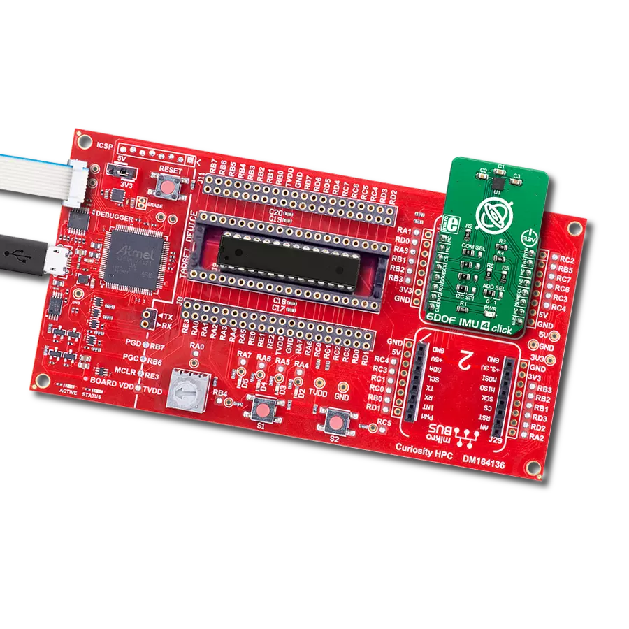
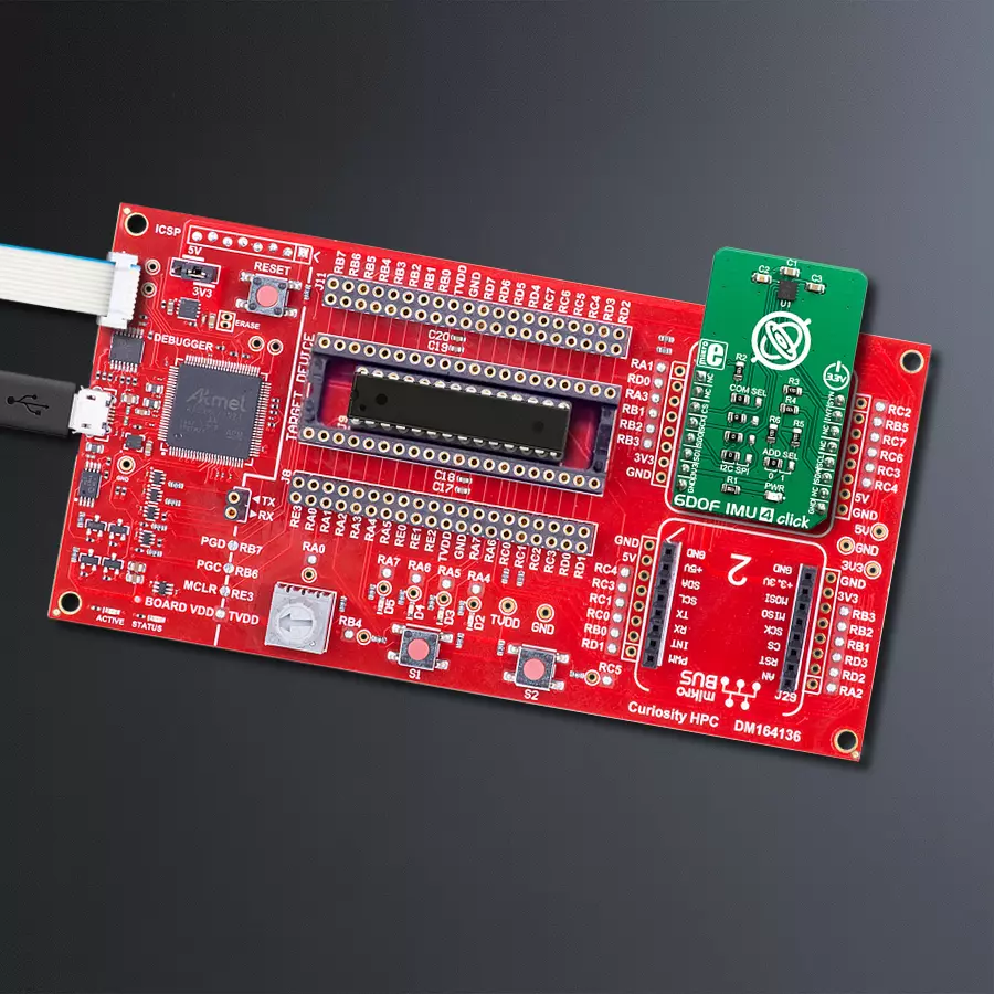
Curiosity HPC
Compiler
NECTO Studio
MCU
PIC18F2553
If you're an engineer, the integration of a 6-axis IMU with a 3-axis gyroscope and accelerometer allows you to develop precise motion control systems for a wide range of applications
A
A
Hardware Overview
How does it work?
6DOF IMU 4 Click is based on the ICM-20602, a high-performance, 6-axis MEMS MotionTracking™ IC from TDK Invensense. It is an advanced, integrated microelectromechanical gyroscope and accelerometer sensor (MEMS). The ICM-20602 is produced using the patented CMOS-MEMS fabrication platform, specialized in MEMS production and its integration with accompanying logic sections, on a wafer level. This allows very high integration and very small dimensions, at an affordable cost. The IC contains a separate accelerometer and gyroscope MEMS on each axis. The output of each MEMS is processed and digitized by a separate sigma-delta 16-bit A/D converter (ADC). Three-axis gyroscope MEMS can be programmed to measure the rotation about each axis, in four different ranges of rotational speed (degrees per angle, DPS): ±250, ±500, ±1000, and ±2000. Three-axis accelerometer MEMS can be programmed to measure the acceleration along each axis, in four different acceleration ranges: ±2g, ±4g, ±8g, and ±16g. The user can select an optimal range for both properties,
depending on the application requirements. The ICM-20602 incorporates a powerful programmable interrupt engine. The interrupt engine can generate a signal on the interrupt pin for several interrupt sources, including FIFO Buffer overflow, Data Ready, I2C Master Error, and I2C Slave Error. The interrupt is routed to the INT pin of the mikroBUS™. A FIFO buffer helps to further reduce the processing load, offering temporary storage for the output data. The MPU6050 features a FIFO buffer with the capacity of 1024 bytes. The user can select which data will be stored in the FIFO buffer: gyro data, accel data, temperature readings, and auxiliary sensor readings. Once the FIFO buffer is full, it will start discarding the oldest data, allowing new data to be written. The FIFO buffer overflow condition can be used to trigger an interrupt, alerting the host MCU about its status. Synchronization with an external digital signal is possible over the FSYNC pin. This pin is routed to the PWM pin of the mikroBUS™, labeled as SYN. The ICM-20602 can be programmed to trigger an interrupt on the FSYN pin activity.
The polarity of the signal pulse applied at the FSYN pin can also be programmed. 6DOF IMU 4 click supports both SPI and I2C communication interfaces, allowing it to be used with a wide range of different MCUs. The communication interface can be chosen by moving SMD jumpers grouped under the COM SEL to an appropriate position (SPI or I2C). The slave I2C address can also be configured by a SMD jumper, when the Click board™ is operated in the I2C mode: a SMD jumper labeled as ADD SEL is used to set the least significant bit (LSB) of the I2C address. When set to 1, the 7-bit I2C slave address becomes 0b1101000x. If set to 0, the address becomes 0b1101001x. The last digit (x) is the R/W bit. This Click board™ uses both I2C and SPI communication interfaces. It is designed to be operated only with 3.3V logic levels. A proper logic voltage level conversion should be performed before the Click board™ is used with MCUs with logic levels of 5V.


Features overview
Development board
Curiosity HPC, standing for Curiosity High Pin Count (HPC) development board, supports 28- and 40-pin 8-bit PIC MCUs specially designed by Microchip for the needs of rapid development of embedded applications. This board has two unique PDIP sockets, surrounded by dual-row expansion headers, allowing connectivity to all pins on the populated PIC MCUs. It also contains a powerful onboard PICkit™ (PKOB), eliminating the need for an external programming/debugging tool, two mikroBUS™ sockets for Click board™ connectivity, a USB connector, a set of indicator LEDs, push button switches and a variable potentiometer. All
these features allow you to combine the strength of Microchip and Mikroe and create custom electronic solutions more efficiently than ever. Each part of the Curiosity HPC development board contains the components necessary for the most efficient operation of the same board. An integrated onboard PICkit™ (PKOB) allows low-voltage programming and in-circuit debugging for all supported devices. When used with the MPLAB® X Integrated Development Environment (IDE, version 3.0 or higher) or MPLAB® Xpress IDE, in-circuit debugging allows users to run, modify, and troubleshoot their custom software and hardware
quickly without the need for additional debugging tools. Besides, it includes a clean and regulated power supply block for the development board via the USB Micro-B connector, alongside all communication methods that mikroBUS™ itself supports. Curiosity HPC development board allows you to create a new application in just a few steps. Natively supported by Microchip software tools, it covers many aspects of prototyping thanks to many number of different Click boards™ (over a thousand boards), the number of which is growing daily.

Microcontroller Overview
MCU Card / MCU

Architecture
PIC
MCU Memory (KB)
32
Silicon Vendor
Microchip
Pin count
28
RAM (Bytes)
2048
Used MCU Pins
mikroBUS™ mapper
Take a closer look
Click board™ Schematic

Step by step
Project assembly

Start by selecting your development board and Click board™. Begin with the Curiosity HPC as your development board.


Software Support
Library Description
This library contains API for 6DOF IMU 4 Click driver.
Key functions:
c6dofimu4_set_sync_pin- Sync Pin Setting functionc6dofimu4_get_data- Data Get functionc6dofimu4_set_fsr- Full Scale Setting function
Open Source
Code example
The complete application code and a ready-to-use project are available through the NECTO Studio Package Manager for direct installation in the NECTO Studio. The application code can also be found on the MIKROE GitHub account.
/*!
 * \file
 * \brief c6DofImu4 Click example
 *
 * # Description
 * This application measures gyroscopic, accelerometer, and temperature data.
 *
 * The demo application is composed of two sections :
 *
 * ## Application Init
 * Initializes I2C interface and performs a device reset and configurations.
 *
 * ## Application Task
 * Waits until data is ready and then reads the all data registers,
  accelerometer, gyroscope and temperature data, and shows results to the uart terminal every 500ms.
 *
 * \author MikroE Team
 *
 */
// ------------------------------------------------------------------- INCLUDES

#include "board.h"
#include "log.h"
#include "c6dofimu4.h"

// ------------------------------------------------------------------ VARIABLES

static c6dofimu4_t c6dofimu4;
static log_t logger;

// ------------------------------------------------------ APPLICATION FUNCTIONS

void application_init ( void )
{
    log_cfg_t log_cfg;
    c6dofimu4_cfg_t cfg;

    /**
     * Logger initialization.
     * Default baud rate: 115200
     * Default log level: LOG_LEVEL_DEBUG
     * @note If USB_UART_RX and USB_UART_TX
     * are defined as HAL_PIN_NC, you will
     * need to define them manually for log to work.
     * See @b LOG_MAP_USB_UART macro definition for detailed explanation.
     */
    LOG_MAP_USB_UART( log_cfg );
    log_init( &logger, &log_cfg );
    log_info( &logger, "---- Application Init ----" );

    //  Click initialization.

    c6dofimu4_cfg_setup( &cfg );
    C6DOFIMU4_MAP_MIKROBUS( cfg, MIKROBUS_1 );
    c6dofimu4_init( &c6dofimu4, &cfg );
    c6dofimu4_reset( &c6dofimu4 );

    c6dofimu4_default_cfg( &c6dofimu4 );
    Delay_ms ( 200 );

    log_printf( &logger, "** 6DOF IMU 4 is initialized **\r\n" );
}

void application_task ( void )
{
    c6dofimu4_axis_t  accel_data;
    c6dofimu4_axis_t  gyro_data;
    uint8_t data_ready;
    int8_t temperature;

    data_ready = c6dofimu4_get_status( &c6dofimu4, C6DOFIMU4_DATA_RDY_INT_MASK );

    while ( data_ready != C6DOFIMU4_DATA_RDY_INT_OCCURED )
    {
        data_ready = c6dofimu4_get_status( &c6dofimu4, C6DOFIMU4_DATA_RDY_INT_MASK );
    }

    c6dofimu4_get_data( &c6dofimu4, &accel_data, &gyro_data, &temperature );

    log_printf( &logger,"** Accelerometer values :\r\n" );
    log_printf( &logger, "* X-axis : %.2lf g ", accel_data.x );
    log_printf( &logger, "* Y-axis : %.2lf g ", accel_data.y );
    log_printf( &logger, "* Z-axis : %.2lf g ", accel_data.z );
    log_printf( &logger,"\r\n" );

    log_printf( &logger,"** Gyroscope values :\r\n" );
    log_printf( &logger, "* X-axis : %.2lf dps ", gyro_data.x );
    log_printf( &logger, "* Y-axis : %.2lf dps ", gyro_data.y );
    log_printf( &logger, "* Z-axis : %.2lf dps ", gyro_data.z );
    log_printf( &logger,"\r\n" );

    log_printf( &logger, "** Temperature value : %d C\r\n", temperature );
    log_printf( &logger,"------------------------------------------------- \r\n" );

    Delay_ms ( 500 );
}

int main ( void )
{
    /* Do not remove this line or clock might not be set correctly. */
    #ifdef PREINIT_SUPPORTED
    preinit();
    #endif

    application_init( );

    for ( ; ; )
    {
        application_task( );
    }

    return 0;
}

// ------------------------------------------------------------------------ END
Additional Support
Resources
Category:Motion


