Upgrade your projects with accurate force sensing using 34-00004 and PIC18F27K40
Capturing forces with precision

Published Jan 23, 2024
Click board™
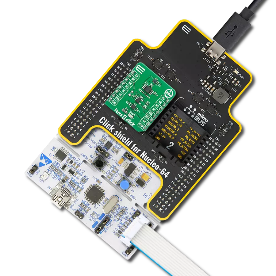
Force 3 Click
Dev. board
Curiosity HPC
Compiler
NECTO Studio
MCU
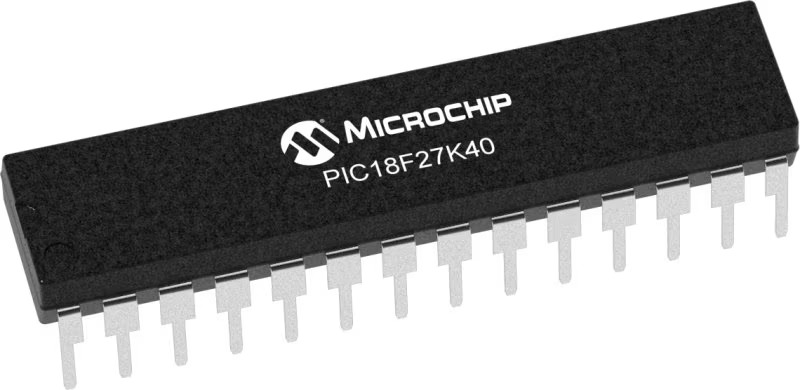
PIC18F27K40
Gain real-time insights into applied forces for improved analysis
A
A
Hardware Overview
How does it work?
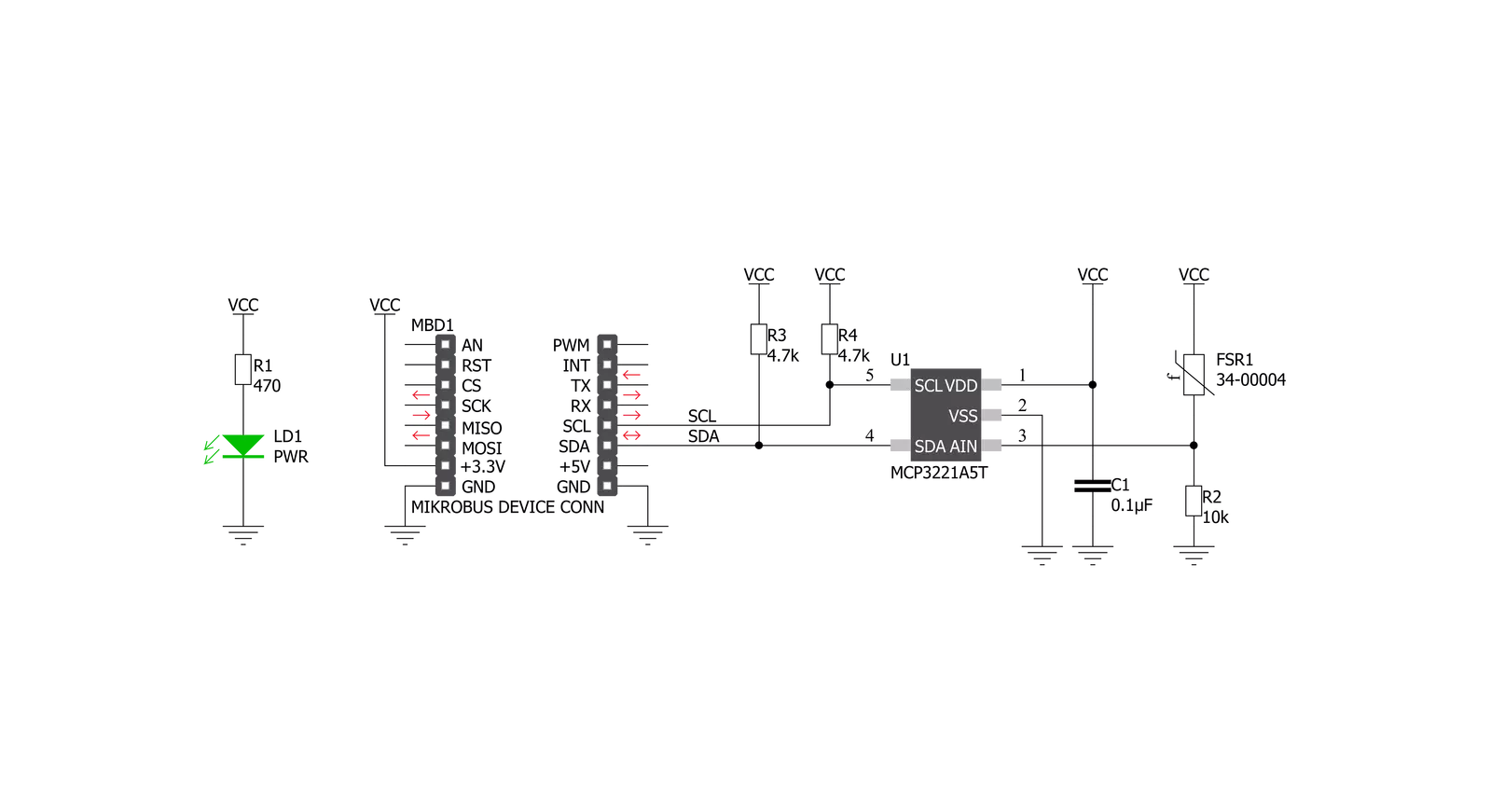
Force 3 Click is based on the FSR 400 series 34-00004 single zone Force Sensing Resistor IC from Interlink Electronics. Force-sensing resistors consist of a conductive polymer, which predictably changes resistance following applying force to its surface. As the force on the sensor is increased, the resistance is decreased. This thin sensor comprises two membranes separated by a spacer around the edges. The top layer of the sensor consists of the area of the force-sensitive layer on the flexible film, while the bottom layer comprises conductive circuit traces on the flexible film. When pressed, the gap between the two membranes gets closed. This shorts the two membranes together with a resistance proportional to an applied force. Force 3 Click also contains all the necessary circuitry
required to obtain precise measurements from the sensor. It communicates with the MCU using the MCP3221, a low-power 12-bit resolution A/D converter with an I2C interface. Data on the I2C bus can be transferred at rates of up to 100 kbit/s in the standard mode and up to 400 kbit/s in the fast mode. Maximum sample rates of 22.3 kSPS are possible with the MCP3221 in a continuous-conversion mode and SCL clock rate of 400 kHz. The sensor is placed in a voltage divider configuration with a fixed resistor R2 (10k). The output voltage is measured across resistor R2 and then sent to the analog pin of the A/D converter MCP3221. Output voltage value was calculated using the voltage divider formula, which was later used in the Test Example to accurately determine
the strength of the applied force. The Test Example is made in such a way that, based on the value of the applied force, it is possible to obtain four output values: Light Touch, Weak Squeeze, Medium Squeeze, and Strong Squeeze. This Click Board™ uses the I2C communication interface. It is designed to be operated only with 3.3V logic levels. A proper logic voltage level conversion should be performed before the Click board™ is used with MCUs with logic levels of 5V. More information about the 34-00004 Force Sensing Resistor can be found in the attached datasheet. However, the Click board™ comes equipped with a library that contains easy-to-use functions and a usage example that may be used as a reference for the development.


Features overview
Development board
Curiosity HPC, standing for Curiosity High Pin Count (HPC) development board, supports 28- and 40-pin 8-bit PIC MCUs specially designed by Microchip for the needs of rapid development of embedded applications. This board has two unique PDIP sockets, surrounded by dual-row expansion headers, allowing connectivity to all pins on the populated PIC MCUs. It also contains a powerful onboard PICkit™ (PKOB), eliminating the need for an external programming/debugging tool, two mikroBUS™ sockets for Click board™ connectivity, a USB connector, a set of indicator LEDs, push button switches and a variable potentiometer. All
these features allow you to combine the strength of Microchip and Mikroe and create custom electronic solutions more efficiently than ever. Each part of the Curiosity HPC development board contains the components necessary for the most efficient operation of the same board. An integrated onboard PICkit™ (PKOB) allows low-voltage programming and in-circuit debugging for all supported devices. When used with the MPLAB® X Integrated Development Environment (IDE, version 3.0 or higher) or MPLAB® Xpress IDE, in-circuit debugging allows users to run, modify, and troubleshoot their custom software and hardware
quickly without the need for additional debugging tools. Besides, it includes a clean and regulated power supply block for the development board via the USB Micro-B connector, alongside all communication methods that mikroBUS™ itself supports. Curiosity HPC development board allows you to create a new application in just a few steps. Natively supported by Microchip software tools, it covers many aspects of prototyping thanks to many number of different Click boards™ (over a thousand boards), the number of which is growing daily.

Microcontroller Overview
MCU Card / MCU
Architecture
PIC
MCU Memory (KB)
128
Silicon Vendor
Microchip
Pin count
28
RAM (Bytes)
3728
Used MCU Pins
mikroBUS™ mapper
Take a closer look
Click board™ Schematic
Step by step
Project assembly

Start by selecting your development board and Click board™. Begin with the Curiosity HPC as your development board.


Track your results in real time
Application Output
1. Application Output - In Debug mode, the 'Application Output' window enables real-time data monitoring, offering direct insight into execution results. Ensure proper data display by configuring the environment correctly using the provided tutorial.

2. UART Terminal - Use the UART Terminal to monitor data transmission via a USB to UART converter, allowing direct communication between the Click board™ and your development system. Configure the baud rate and other serial settings according to your project's requirements to ensure proper functionality. For step-by-step setup instructions, refer to the provided tutorial.

3. Plot Output - The Plot feature offers a powerful way to visualize real-time sensor data, enabling trend analysis, debugging, and comparison of multiple data points. To set it up correctly, follow the provided tutorial, which includes a step-by-step example of using the Plot feature to display Click board™ readings. To use the Plot feature in your code, use the function: plot(*insert_graph_name*, variable_name);. This is a general format, and it is up to the user to replace 'insert_graph_name' with the actual graph name and 'variable_name' with the parameter to be displayed.

Software Support
Library Description
This library contains API for Force 3 Click driver.
Key functions:
force3_read_raw_data- Read 12bit raw data
Open Source
Code example
The complete application code and a ready-to-use project are available through the NECTO Studio Package Manager for direct installation in the NECTO Studio. The application code can also be found on the MIKROE GitHub account.
/*!
 * \file
 * \brief Force3 Click example
 *
 * # Description
 * This application demonstrates the use of Force 3 Click board.
 *
 * The demo application is composed of two sections :
 *
 * ## Application Init
 * Initializes the driver and makes an initial log.
 *
 * ## Application Task
 * Reads the sensor raw data and displays it on the USB UART.
 *
 * \author MikroE Team
 *
 */
// ------------------------------------------------------------------- INCLUDES

#include "board.h"
#include "log.h"
#include "force3.h"

// ------------------------------------------------------------------ VARIABLES

static force3_t force3;
static log_t logger;

// ------------------------------------------------------ APPLICATION FUNCTIONS

void application_init ( void )
{
    log_cfg_t log_cfg;
    force3_cfg_t cfg;

    /**
     * Logger initialization.
     * Default baud rate: 115200
     * Default log level: LOG_LEVEL_DEBUG
     * @note If USB_UART_RX and USB_UART_TX
     * are defined as HAL_PIN_NC, you will
     * need to define them manually for log to work.
     * See @b LOG_MAP_USB_UART macro definition for detailed explanation.
     */
    LOG_MAP_USB_UART( log_cfg );
    log_init( &logger, &log_cfg );
    log_info( &logger, "---- Application Init ----" );

    //  Click initialization.

    force3_cfg_setup( &cfg );
    FORCE3_MAP_MIKROBUS( cfg, MIKROBUS_1 );
    force3_init( &force3, &cfg );
}

void application_task ( void )
{
    uint16_t raw_data;

    raw_data = force3_read_raw_data( &force3 );
    log_printf( &logger, "Raw data: %d \r\n", raw_data );

    if ( ( raw_data > 5 ) && ( raw_data <= 200 ) )
    {
       log_printf( &logger, ">> Light touch \r\n" );
    }
    else if ( ( raw_data > 200 ) && ( raw_data <= 500 ) )
    {
       log_printf( &logger, ">> Light squeeze \r\n" );
    }
    else if ( ( raw_data > 500 ) && ( raw_data <= 800 ) )
    {
       log_printf( &logger, ">> Medium squeeze \r\n" );
    }
    else if ( raw_data > 800 )
    {
       log_printf( &logger, ">> Big squeeze \r\n" );
    }

    log_printf( &logger, "----------------------\r\n" );
    Delay_ms ( 1000 );
}

int main ( void )
{
    /* Do not remove this line or clock might not be set correctly. */
    #ifdef PREINIT_SUPPORTED
    preinit();
    #endif

    application_init( );

    for ( ; ; )
    {
        application_task( );
    }

    return 0;
}

// ------------------------------------------------------------------------ END