Experience the future of magnetic field detection with ALS31300 and PIC18F57Q43
A new dimension of insight: Discover our 3D magnetic sensor's X, Y, and Z capabilities

Published Feb 13, 2024
Click board™
3D Hall 9 Click
Dev. board
Curiosity Nano with PIC18F57Q43
Compiler
NECTO Studio
MCU
PIC18F57Q43
From industrial automation to scientific research, our 3D magnetic field strength detector opens doors to endless possibilities, ensuring accurate measurements across all three dimensions
A
A
Hardware Overview
How does it work?
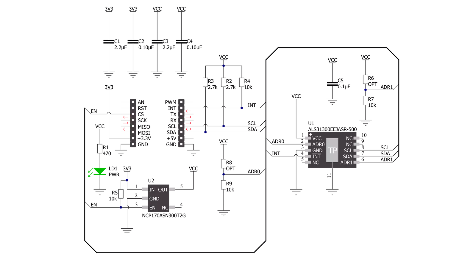
3D Hall 9 Click is based on the ALS31300, a 3D linear Hall-effect sensor used to detect the strength of a magnetic field in all three dimensions (X, Y, and Z axes) from Allegro Microsystems. The ALS31300 provides a 12-bit digital output value proportional to the magnetic field generally applied to any of the Hall elements alongside a 12-bit temperature output representing the junction temperature of the IC. The quiescent output value (zero magnetic fields used) is at mid-scale. The ALS31300 has a factory-programmed sensitivity range of ±500G, suitable for 3D linear or 2D angle sensing applications. Power management on the ALS31300 is user-selectable and highly configurable, allowing for system-level optimization of current consumption and performance. It supports three power modes: Active, Sleep, and Low-Power Duty Cycle Mode (LPDCM). The operating mode of the ALS31300 will
be determined by the selected proper value of the 0x27 register. More information on the operational modes can be found in the attached datasheet. 3D Hall 9 Click communicates with MCU using the standard I2C 2-Wire interface to read data and configure settings, supporting Standard Mode operation with a clock frequency of 100kHz and Fast Mode up to 400kHz. It provides data in digital format of 12 bits corresponding to the magnetic field measured in each X, Y, and Z axes. The ALS31300 also requires a supply voltage of 3V to work regularly. Therefore, a small LDO regulator, NCP170 from ON Semiconductor, provides a 3V out of mikroBUS™ 3V3 power rail. This Click board™ also uses the Enable pin labeled as EN and routed to the CS pin of the mikroBUS™ socket to optimize power consumption, used for its power ON/OFF purposes. The ALS31300 provides the ability to set different I2C slave addresses (16
unique addresses) by populating the appropriate resistors (R8 and R6), thus forming a voltage divider with a voltage value that corresponds to the desired I2C address. It also possesses an additional interrupt signal, routed on the INT pin of the mikroBUS™ socket. It integrates the detection and reporting of significant changes in an applied magnetic field (independently turned on or off for each of the three axes). An interrupt event is initiated when the applied magnetic field forces the ADC output to a value greater than or equal to the user-programmed threshold. This Click board™ can be operated only with a 3.3V logic voltage level. The board must perform appropriate logic voltage level conversion before using MCUs with different logic levels. Also, it comes equipped with a library containing functions and an example code that can be used as a reference for further development.


Features overview
Development board
PIC18F57Q43 Curiosity Nano evaluation kit is a cutting-edge hardware platform designed to evaluate microcontrollers within the PIC18-Q43 family. Central to its design is the inclusion of the powerful PIC18F57Q43 microcontroller (MCU), offering advanced functionalities and robust performance. Key features of this evaluation kit include a yellow user LED and a responsive
mechanical user switch, providing seamless interaction and testing. The provision for a 32.768kHz crystal footprint ensures precision timing capabilities. With an onboard debugger boasting a green power and status LED, programming and debugging become intuitive and efficient. Further enhancing its utility is the Virtual serial port (CDC) and a debug GPIO channel (DGI
GPIO), offering extensive connectivity options. Powered via USB, this kit boasts an adjustable target voltage feature facilitated by the MIC5353 LDO regulator, ensuring stable operation with an output voltage ranging from 1.8V to 5.1V, with a maximum output current of 500mA, subject to ambient temperature and voltage constraints.

Microcontroller Overview
MCU Card / MCU

Architecture
PIC
MCU Memory (KB)
128
Silicon Vendor
Microchip
Pin count
48
RAM (Bytes)
8196
You complete me!
Accessories
Curiosity Nano Base for Click boards is a versatile hardware extension platform created to streamline the integration between Curiosity Nano kits and extension boards, tailored explicitly for the mikroBUS™-standardized Click boards and Xplained Pro extension boards. This innovative base board (shield) offers seamless connectivity and expansion possibilities, simplifying experimentation and development. Key features include USB power compatibility from the Curiosity Nano kit, alongside an alternative external power input option for enhanced flexibility. The onboard Li-Ion/LiPo charger and management circuit ensure smooth operation for battery-powered applications, simplifying usage and management. Moreover, the base incorporates a fixed 3.3V PSU dedicated to target and mikroBUS™ power rails, alongside a fixed 5.0V boost converter catering to 5V power rails of mikroBUS™ sockets, providing stable power delivery for various connected devices.

Used MCU Pins
mikroBUS™ mapper
Take a closer look
Click board™ Schematic
Step by step
Project assembly

Start by selecting your development board and Click board™. Begin with the Curiosity Nano with PIC18F57Q43 as your development board.


Track your results in real time
Application Output
1. Application Output - In Debug mode, the 'Application Output' window enables real-time data monitoring, offering direct insight into execution results. Ensure proper data display by configuring the environment correctly using the provided tutorial.

2. UART Terminal - Use the UART Terminal to monitor data transmission via a USB to UART converter, allowing direct communication between the Click board™ and your development system. Configure the baud rate and other serial settings according to your project's requirements to ensure proper functionality. For step-by-step setup instructions, refer to the provided tutorial.

3. Plot Output - The Plot feature offers a powerful way to visualize real-time sensor data, enabling trend analysis, debugging, and comparison of multiple data points. To set it up correctly, follow the provided tutorial, which includes a step-by-step example of using the Plot feature to display Click board™ readings. To use the Plot feature in your code, use the function: plot(*insert_graph_name*, variable_name);. This is a general format, and it is up to the user to replace 'insert_graph_name' with the actual graph name and 'variable_name' with the parameter to be displayed.

Software Support
Library Description
This library contains API for 3D Hall 9 Click driver.
Key functions:
c3dhall9_write_register- This function writes a desired data to the selected register by using I2C serial interface.c3dhall9_read_register- This function reads a desired data from the selected register by using I2C serial interface.c3dhall9_read_data- This function reads new data which consists of X, Y, and Z axis values in Gauss, and temperature in Celsius. It also calculates the angles between all axes in Degrees based on the raw axes data read.
Open Source
Code example
The complete application code and a ready-to-use project are available through the NECTO Studio Package Manager for direct installation in the NECTO Studio. The application code can also be found on the MIKROE GitHub account.
/*!
 * @file main.c
 * @brief 3DHall9 Click example
 *
 * # Description
 * This example demonstrates the use of 3D Hall 9 Click board by reading the magnetic
 * flux density from 3 axes as well as the angles between axes and the sensor temperature.
 *
 * The demo application is composed of two sections :
 *
 * ## Application Init
 * Initializes the driver and the Click board.
 *
 * ## Application Task
 * Reads the new data from the sensor approximately every 300ms and displays
 * the measurement values on the USB UART.
 *
 * @author Stefan Filipovic
 *
 */

#include "board.h"
#include "log.h"
#include "c3dhall9.h"

static c3dhall9_t c3dhall9;
static log_t logger;

void application_init ( void )
{
    log_cfg_t log_cfg;  /**< Logger config object. */
    c3dhall9_cfg_t c3dhall9_cfg;  /**< Click config object. */

    /**
     * Logger initialization.
     * Default baud rate: 115200
     * Default log level: LOG_LEVEL_DEBUG
     * @note If USB_UART_RX and USB_UART_TX
     * are defined as HAL_PIN_NC, you will
     * need to define them manually for log to work.
     * See @b LOG_MAP_USB_UART macro definition for detailed explanation.
     */
    LOG_MAP_USB_UART( log_cfg );
    log_init( &logger, &log_cfg );
    log_info( &logger, " Application Init " );

    // Click initialization.
    c3dhall9_cfg_setup( &c3dhall9_cfg );
    C3DHALL9_MAP_MIKROBUS( c3dhall9_cfg, MIKROBUS_1 );
    if ( I2C_MASTER_ERROR == c3dhall9_init( &c3dhall9, &c3dhall9_cfg ) )
    {
        log_error( &logger, " Communication init." );
        for ( ; ; );
    }

    if ( C3DHALL9_ERROR == c3dhall9_default_cfg ( &c3dhall9 ) )
    {
        log_error( &logger, " Default configuration." );
        for ( ; ; );
    }

    log_info( &logger, " Application Task " );
}

void application_task ( void )
{
    c3dhall9_data_t sensor_data;

    if ( C3DHALL9_OK == c3dhall9_read_data ( &c3dhall9, &sensor_data ) )
    {
        log_printf( &logger, " X-axis: %.1f Gauss\r\n", sensor_data.x_axis );
        log_printf( &logger, " Y-axis: %.1f Gauss\r\n", sensor_data.y_axis );
        log_printf( &logger, " Z-axis: %.1f Gauss\r\n", sensor_data.z_axis );
        log_printf( &logger, " Angle XY: %.1f Degrees\r\n", sensor_data.angle_xy );
        log_printf( &logger, " Angle XZ: %.1f Degrees\r\n", sensor_data.angle_xz );
        log_printf( &logger, " Angle YZ: %.1f Degrees\r\n", sensor_data.angle_yz );
        log_printf( &logger, " Temperature: %.2f Celsius\r\n\n", sensor_data.temperature );
        Delay_ms ( 300 );
    }
}

int main ( void )
{
    /* Do not remove this line or clock might not be set correctly. */
    #ifdef PREINIT_SUPPORTED
    preinit();
    #endif

    application_init( );

    for ( ; ; )
    {
        application_task( );
    }

    return 0;
}

// ------------------------------------------------------------------------ END
Additional Support
Resources
Category:Magnetic


