Accurately monitor and locate valuable assets in indoor environments with Sera NX040 (453-00174C) and PIC18F57Q43
Ultra-WideBand (UWB) and Bluetooth LE for exceptional ranging accuracy of less than ±10cm

Published Aug 19, 2024
Click board™
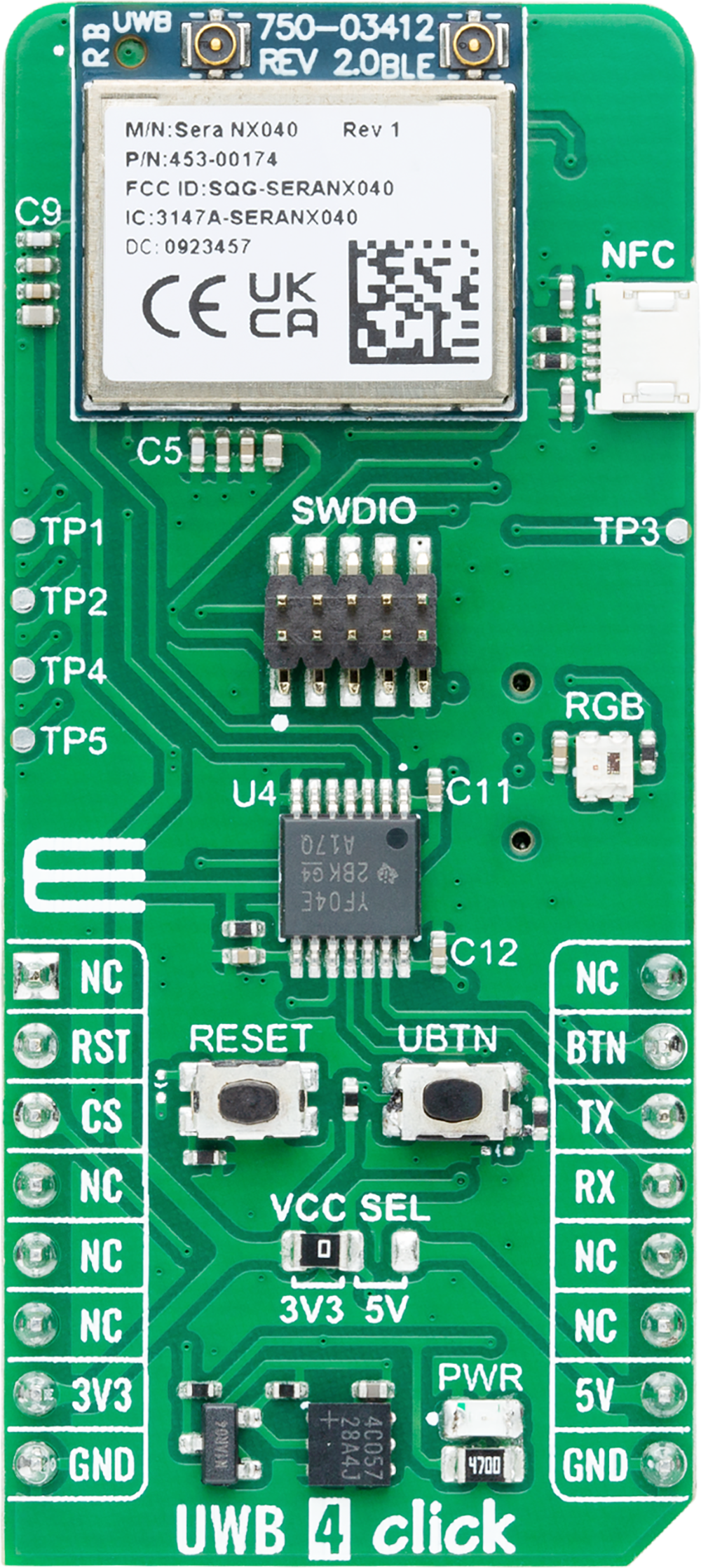
UWB 4 Click
Dev. board
Curiosity Nano with PIC18F57Q43
Compiler
NECTO Studio
MCU
PIC18F57Q43
Combine UWB for precise ranging with Bluetooth LE for wireless communication and data transfer for precise indoor positioning and location-based applications
A
A
Hardware Overview
How does it work?
UWB 4 Click is based on the Sera NX040 (453-00174C), an advanced UWB/BLE module equipped with external antenna connectors from Ezurio. The module features top-tier silicon: NXP's SR040 chipset for ultra-wideband (UWB) and Nordic Semiconductor's nRF52833 for Bluetooth LE, providing outstanding performance in precise positioning and wireless communication. Moreover, the module is pre-calibrated for regulatory compliance and optimized for superior ranging performance across various temperatures and UWB antenna implementations, making this Click board™ ideal for precise indoor positioning and location-based applications, such as asset tracking, navigation, and industrial automation. As mentioned, at the heart of the Sera NX040 is the NXP SR040 Ultra-Wideband Transceiver, which supports IEEE 802.15.4/4z High Precision Ranging (HPR) UWB operations. It includes a fully embedded FiRa-compliant MAC and PHY, allowing for seamless Two-Way Ranging (TWR) sessions in both initiator and responder modes, as well as Blink mode operation within Time Difference of Arrival (TDoA) systems. The SR040 achieves exceptional ranging accuracy of less than ±10cm, with a typical receiver sensitivity of -92dBm. Additionally, the module incorporates the Nordic Semiconductor nRF52833 chipset, a fully certified Bluetooth SoC that supports Bluetooth (LE) 5.4 for the efficient
provisioning, setup, and control of UWB ranging sessions. The nRF52833 offers a maximum transmit output power of +8dBm and a typical receive sensitivity of -96dBm. The Sera NX040 achieves communication with the host MCU via a UART interface via standard RX and TX pins. With a default baud rate of 115200bps, this setup ensures efficient and reliable data transfer. In addition to UART, this board is equipped with a USB type-C connector for USB 2.0 FS (Full Speed, 12Mbps), enabling direct connection to the Sera NX040 module's USB port for flexible integration. When using the USB interface, the entire system is powered by a 3.3V supply provided by the MCP1826 LDO regulator, which converts the 5V from the USB to 3.3V. For development and debugging, the module provides a SWDIO header that grants access to the nRF52833's SWD (JTAG) interface, making it compatible with the Nordic SDK. This interface is crucial for developers leveraging advanced features and performing in-depth testing. Comprehensive support for USB drivers is available through the Nordic SDK, enhancing the module's versatility in various development environments. In addition to the interface pins, this Click board™ features a reset pin (RST) and a RESET button for module resetting. It also includes a user pin (BTN) and button (UBTN) for interactive control over the
program flow. An RGB LED acts as a user-configurable red LED indicator, providing visual feedback for various statuses, such as UART messaging, boot processes, or debugger commands. The board also includes an NFC antenna connector for NFC applications and test points for debugging and monitoring. TP1 and TP2 serve as the second UART pins of the Sera NX040, while TP3, TP4, and TP5 provide access to the SR040 RST, SWCLK, and SWDIO pins, respectively. These features enable easy access to testing and development, making the board highly versatile for a wide range of applications. At the bottom of the UWB 4 Click, there are LP Cut traces. By cutting these traces, you can achieve low power consumption by disconnecting the PWR LED and ClickID from the circuit, resulting in additional power savings. This Click board™ can operate with both 3.3V and 5V logic voltage levels selected via the VCC SEL jumper. Given that the Sera NX040 module operates at 3.3V, a logic-level translator, the TXS0104, is also used for proper operation and an accurate signal-level translation. This way, both 3.3V and 5V capable MCUs can use the communication lines properly. Also, this Click board™ comes equipped with a library containing easy-to-use functions and an example code that can be used as a reference for further development.

Features overview
Development board
PIC18F57Q43 Curiosity Nano evaluation kit is a cutting-edge hardware platform designed to evaluate microcontrollers within the PIC18-Q43 family. Central to its design is the inclusion of the powerful PIC18F57Q43 microcontroller (MCU), offering advanced functionalities and robust performance. Key features of this evaluation kit include a yellow user LED and a responsive
mechanical user switch, providing seamless interaction and testing. The provision for a 32.768kHz crystal footprint ensures precision timing capabilities. With an onboard debugger boasting a green power and status LED, programming and debugging become intuitive and efficient. Further enhancing its utility is the Virtual serial port (CDC) and a debug GPIO channel (DGI
GPIO), offering extensive connectivity options. Powered via USB, this kit boasts an adjustable target voltage feature facilitated by the MIC5353 LDO regulator, ensuring stable operation with an output voltage ranging from 1.8V to 5.1V, with a maximum output current of 500mA, subject to ambient temperature and voltage constraints.

Microcontroller Overview
MCU Card / MCU

Architecture
PIC
MCU Memory (KB)
128
Silicon Vendor
Microchip
Pin count
48
RAM (Bytes)
8196
You complete me!
Accessories
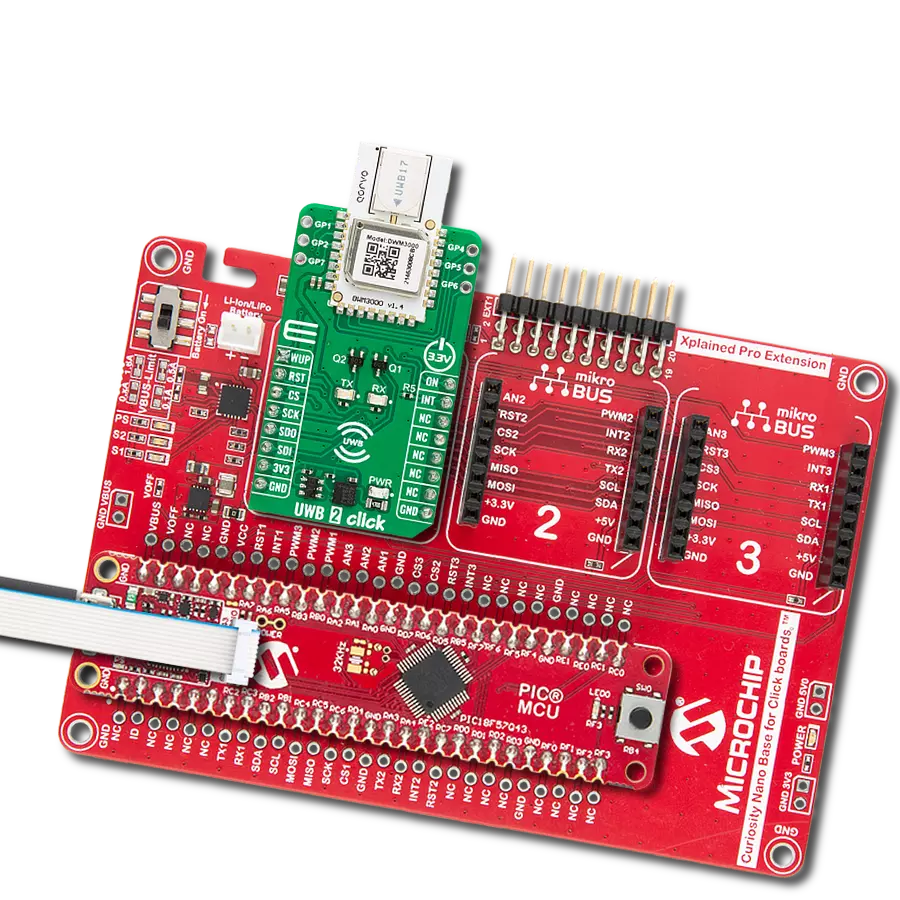
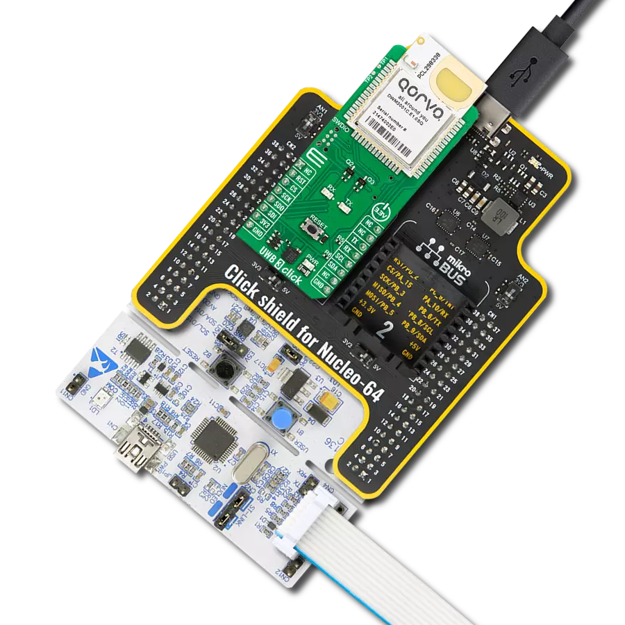
Curiosity Nano Base for Click boards is a versatile hardware extension platform created to streamline the integration between Curiosity Nano kits and extension boards, tailored explicitly for the mikroBUS™-standardized Click boards and Xplained Pro extension boards. This innovative base board (shield) offers seamless connectivity and expansion possibilities, simplifying experimentation and development. Key features include USB power compatibility from the Curiosity Nano kit, alongside an alternative external power input option for enhanced flexibility. The onboard Li-Ion/LiPo charger and management circuit ensure smooth operation for battery-powered applications, simplifying usage and management. Moreover, the base incorporates a fixed 3.3V PSU dedicated to target and mikroBUS™ power rails, alongside a fixed 5.0V boost converter catering to 5V power rails of mikroBUS™ sockets, providing stable power delivery for various connected devices.

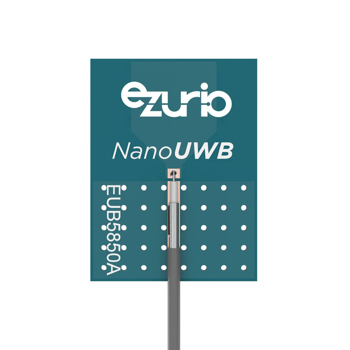
EUB5850A3S-10MH4L NanoUWB antenna provides robust coverage across UWB Channels 5, 6, 7, 8, and 9, operating within the 5850-8250 MHz frequency range. With a 3-dBi gain, this antenna ensures optimal performance for ultra-wideband applications. Its quick and easy installation, combined with adhesive that holds firmly during humidity exposure and hot/cold cycles, makes it a reliable choice for diverse environments. RoHS-compliant and versatile, it can be installed on various non-conductive surfaces, different thicknesses, and even in free space, offering flexibility for both flat and open installations.
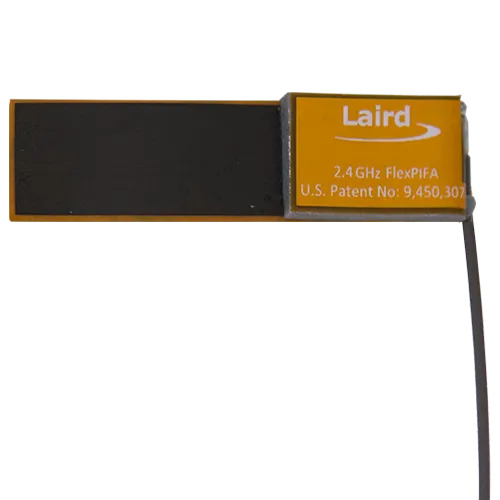
001-0022 FlexPIFA antenna is designed for 2.4 GHz BLE applications, offering a frequency range of 2400-2480 MHz with a peak gain of +2.0 dBi and an average gain better than -1.5 dBi. Featuring a linear polarization and a VSWR of less than 2.0:1, this antenna ensures efficient signal transmission with a 50 Ω impedance. It is quick to install and RoHS-compliant, with adhesive that remains secure even in challenging conditions such as humidity and temperature fluctuations. The FlexPIFA can be mounted on various non-conductive surfaces, near metals, or even close to the human body, making it ideal for wearable and compact devices.
Used MCU Pins
mikroBUS™ mapper
Take a closer look
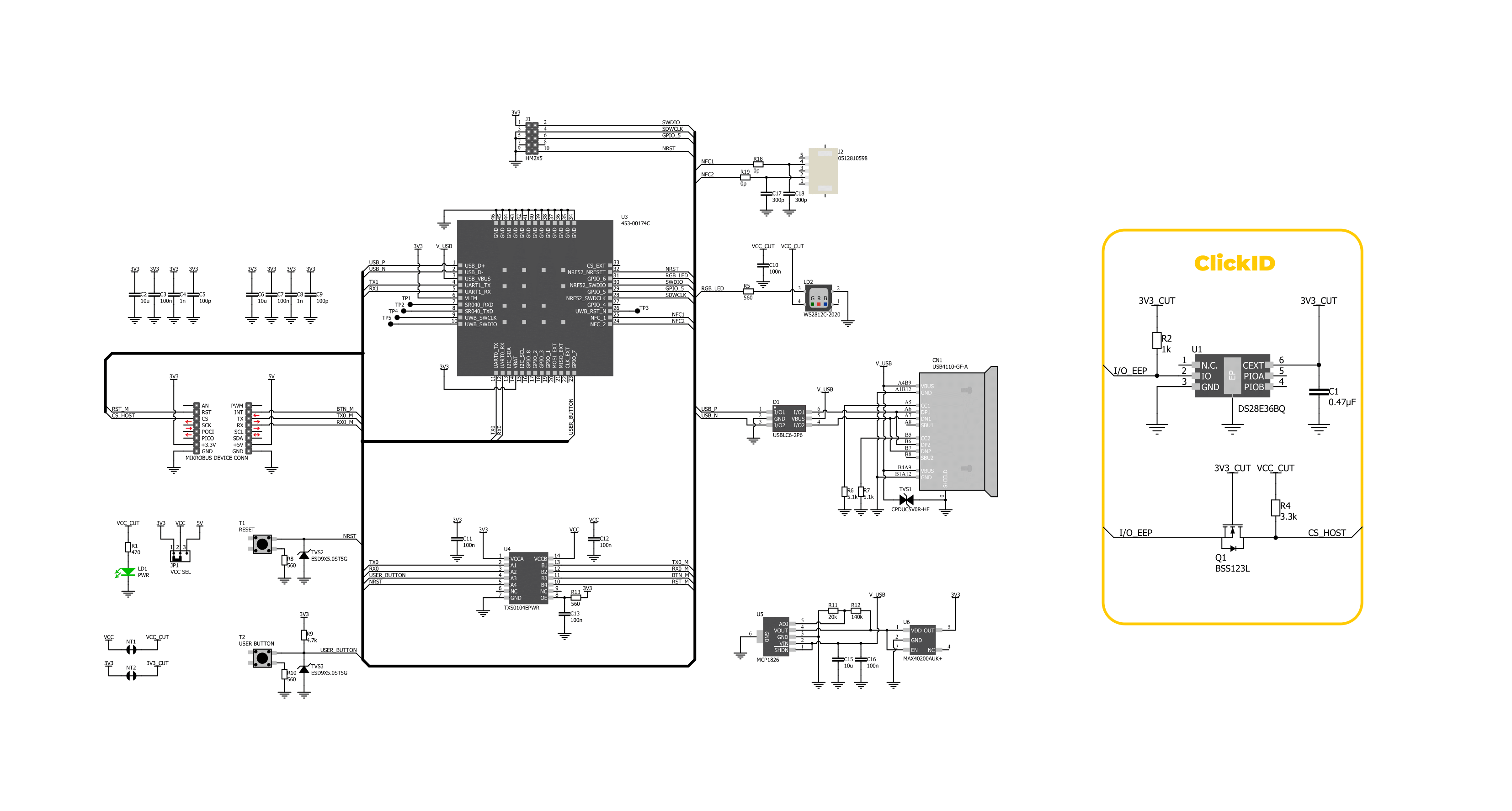
Click board™ Schematic
Step by step
Project assembly

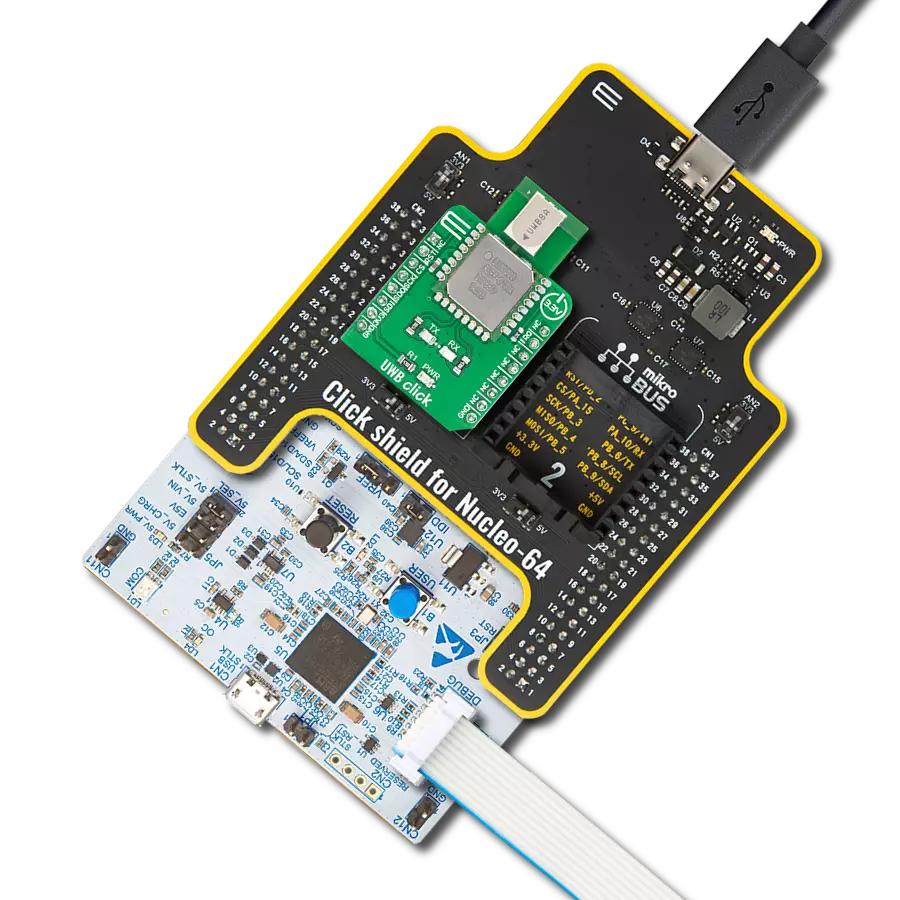
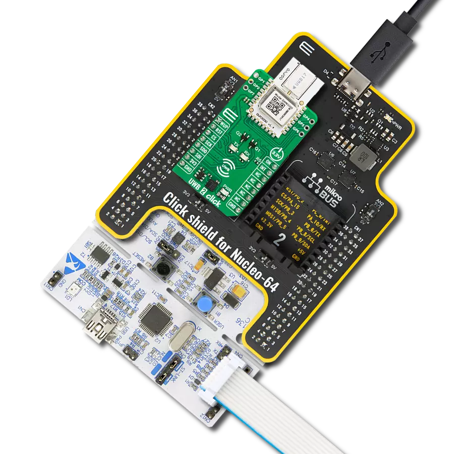
Start by selecting your development board and Click board™. Begin with the Curiosity Nano with PIC18F57Q43 as your development board.


Software Support
Library Description
This library contains API for UWB 4 Click driver.
Key functions:
uwb4_cmd_run- This function sends a specified command to the click module.uwb4_cmd_set- This function sets a value to a specified command of the click module.uwb4_reset_device- This function resets the device by toggling the reset pin logic state.
Open Source
Code example
The complete application code and a ready-to-use project are available through the NECTO Studio Package Manager for direct installation in the NECTO Studio. The application code can also be found on the MIKROE GitHub account.
/*!
 * @file main.c
 * @brief UWB 4 Click Example.
 *
 * # Description
 * This example demonstrates the use of UWB 4 Click board by showing
 * the UWB ranging between two Click boards configured as initiator and responder.
 *
 * The demo application is composed of two sections :
 *
 * ## Application Init
 * Initializes the driver and logger.
 *
 * ## Application Task
 * Application task is split in few stages:
 *  - UWB4_POWER_UP:
 * Powers up the device and reads system information.
 *  - UWB4_CONFIG_EXAMPLE:
 * Configures device for UWB ranging.
 *  - UWB4_EXAMPLE:
 * Reads and parses the UWB ranging information.
 *
 * ## Additional Function
 * - static void uwb4_clear_app_buf ( void )
 * - static void uwb4_log_app_buf ( void )
 * - static err_t uwb4_process ( uwb4_t *ctx )
 * - static err_t uwb4_read_response ( uwb4_t *ctx, uint8_t *rsp )
 * - static err_t uwb4_power_up ( uwb4_t *ctx )
 * - static err_t uwb4_config_example ( uwb4_t *ctx )
 * - static err_t uwb4_example ( uwb4_t *ctx )
 *
 * @author Stefan Filipovic
 *
 */

#include "board.h"
#include "log.h"
#include "uwb4.h"
#include "generic_pointer.h"

// Comment out the line below to switch the example mode to responder
#define EXAMPLE_INITIATOR

// Default config for initiator and responder examples
#ifdef EXAMPLE_INITIATOR
    #define UWB_SESSION_ID          "1234"
    #define UWB_ROLE                "0"
    #define UWB_LOCAL_ADDRESS       "1111"
    #define UWB_REMOTE_ADDRESS      "2222"
    #define UWB_RANGING_INTERVAL    "500"
#else
    #define UWB_SESSION_ID          "1234"
    #define UWB_ROLE                "1"
    #define UWB_LOCAL_ADDRESS       "2222"
    #define UWB_REMOTE_ADDRESS      "1111"
    #define UWB_RANGING_INTERVAL    "500"
#endif

static uwb4_t uwb4;
static log_t logger;

// Application buffer size
#define APP_BUFFER_SIZE             256
#define PROCESS_BUFFER_SIZE         256

static uint8_t app_buf[ APP_BUFFER_SIZE ] = { 0 };
static int32_t app_buf_len = 0;

/**
 * @brief Example states.
 * @details Predefined enum values for application example state.
 */
typedef enum
{
    UWB4_POWER_UP = 1,
    UWB4_CONFIG_EXAMPLE,
    UWB4_EXAMPLE

} uwb4_app_state_t;

static uwb4_app_state_t app_state = UWB4_POWER_UP;

/**
 * @brief UWB 4 clearing application buffer.
 * @details This function clears memory of application buffer and reset its length.
 * @note None.
 */
static void uwb4_clear_app_buf ( void );

/**
 * @brief UWB 4 log application buffer.
 * @details This function logs data from application buffer to USB UART.
 * @note None.
 */
static void uwb4_log_app_buf ( void );

/**
 * @brief UWB 4 data reading function.
 * @details This function reads data from device and concatenates data to application buffer.
 * @param[in] ctx : Click context object.
 * See #uwb4_t object definition for detailed explanation.
 * @return @li @c  0 - Read some data.
 *         @li @c -1 - Nothing is read.
 * See #err_t definition for detailed explanation.
 * @note None.
 */
static err_t uwb4_process ( uwb4_t *ctx );

/**
 * @brief UWB 4 read response function.
 * @details This function waits for a response message, reads and displays it on the USB UART.
 * @param[in] ctx : Click context object.
 * See #uwb4_t object definition for detailed explanation.
 * @param[in] rsp  Expected response.
 * @return @li @c  0 - OK response.
 *         @li @c -2 - Timeout error.
 *         @li @c -3 - Command error.
 * See #err_t definition for detailed explanation.
 * @note None.
 */
static err_t uwb4_read_response ( uwb4_t *ctx, uint8_t *rsp );

/**
 * @brief UWB 4 power up function.
 * @details This function powers up the device and reads system information.
 * @param[in] ctx : Click context object.
 * See #uwb4_t object definition for detailed explanation.
 * @return @li @c    0 - OK.
 *         @li @c != 0 - Read response error.
 * See #err_t definition for detailed explanation.
 * @note None.
 */
static err_t uwb4_power_up ( uwb4_t *ctx );

/**
 * @brief UWB 4 config example function.
 * @details This function configures device for UWB ranging.
 * @param[in] ctx : Click context object.
 * See #uwb4_t object definition for detailed explanation.
 * @return @li @c    0 - OK.
 *         @li @c != 0 - Read response error.
 * See #err_t definition for detailed explanation.
 * @note None.
 */
static err_t uwb4_config_example ( uwb4_t *ctx );

/**
 * @brief UWB 4 example function.
 * @details This function reads and parses the UWB ranging information.
 * @param[in] ctx : Click context object.
 * See #uwb4_t object definition for detailed explanation.
 * @return @li @c    0 - OK.
 *         @li @c != 0 - Read response error.
 * See #err_t definition for detailed explanation.
 * @note None.
 */
static err_t uwb4_example ( uwb4_t *ctx );

void application_init ( void )
{
    log_cfg_t log_cfg;  /**< Logger config object. */
    uwb4_cfg_t uwb4_cfg;  /**< Click config object. */

    /**
     * Logger initialization.
     * Default baud rate: 115200
     * Default log level: LOG_LEVEL_DEBUG
     * @note If USB_UART_RX and USB_UART_TX
     * are defined as HAL_PIN_NC, you will
     * need to define them manually for log to work.
     * See @b LOG_MAP_USB_UART macro definition for detailed explanation.
     */
    LOG_MAP_USB_UART( log_cfg );
    log_init( &logger, &log_cfg );
    log_info( &logger, " Application Init " );

    // Click initialization.
    uwb4_cfg_setup( &uwb4_cfg );
    UWB4_MAP_MIKROBUS( uwb4_cfg, MIKROBUS_1 );
    if ( UART_ERROR == uwb4_init( &uwb4, &uwb4_cfg ) )
    {
        log_error( &logger, " Communication init." );
        for ( ; ; );
    }

    log_info( &logger, " Application Task " );

    app_state = UWB4_POWER_UP;
    log_printf( &logger, ">>> APP STATE - POWER UP <<<\r\n\n" );
}

void application_task ( void )
{
    switch ( app_state )
    {
        case UWB4_POWER_UP:
        {
            if ( UWB4_OK == uwb4_power_up( &uwb4 ) )
            {
                app_state = UWB4_CONFIG_EXAMPLE;
                log_printf( &logger, ">>> APP STATE - CONFIG EXAMPLE <<<\r\n\n" );
            }
            break;
        }
        case UWB4_CONFIG_EXAMPLE:
        {
            if ( UWB4_OK == uwb4_config_example( &uwb4 ) )
            {
                app_state = UWB4_EXAMPLE;
                log_printf( &logger, ">>> APP STATE - EXAMPLE <<<\r\n\n" );
            }
            break;
        }
        case UWB4_EXAMPLE:
        {
            uwb4_example( &uwb4 );
            break;
        }
        default:
        {
            log_error( &logger, " APP STATE." );
            break;
        }
    }
}

int main ( void )
{
    /* Do not remove this line or clock might not be set correctly. */
    #ifdef PREINIT_SUPPORTED
    preinit();
    #endif

    application_init( );

    for ( ; ; )
    {
        application_task( );
    }

    return 0;
}

static void uwb4_clear_app_buf ( void )
{
    memset( app_buf, 0, app_buf_len );
    app_buf_len = 0;
}

static void uwb4_log_app_buf ( void )
{
    for ( int32_t buf_cnt = 0; buf_cnt < app_buf_len; buf_cnt++ )
    {
        log_printf( &logger, "%c", app_buf[ buf_cnt ] );
    }
}

static err_t uwb4_process ( uwb4_t *ctx )
{
    uint8_t rx_buf[ PROCESS_BUFFER_SIZE ] = { 0 };
    int32_t overflow_bytes = 0;
    int32_t rx_cnt = 0;
    int32_t rx_size = uwb4_generic_read( ctx, rx_buf, PROCESS_BUFFER_SIZE );
    if ( ( rx_size > 0 ) && ( rx_size <= APP_BUFFER_SIZE ) )
    {
        if ( ( app_buf_len + rx_size ) > APP_BUFFER_SIZE )
        {
            overflow_bytes = ( app_buf_len + rx_size ) - APP_BUFFER_SIZE;
            app_buf_len = APP_BUFFER_SIZE - rx_size;
            memmove ( app_buf, &app_buf[ overflow_bytes ], app_buf_len );
            memset ( &app_buf[ app_buf_len ], 0, overflow_bytes );
        }
        for ( rx_cnt = 0; rx_cnt < rx_size; rx_cnt++ )
        {
            if ( rx_buf[ rx_cnt ] )
            {
                app_buf[ app_buf_len++ ] = rx_buf[ rx_cnt ];
            }
        }
        return UWB4_OK;
    }
    return UWB4_ERROR;
}

static err_t uwb4_read_response ( uwb4_t *ctx, uint8_t *rsp )
{
    #define READ_RESPONSE_TIMEOUT_MS    30000
    uint32_t timeout_cnt = 0;
    uwb4_clear_app_buf ( );
    uwb4_process( ctx );
    while ( ( 0 == strstr( app_buf, rsp ) ) &&
            ( 0 == strstr( app_buf, UWB4_RSP_ERROR ) ) )
    {
        uwb4_process( ctx );
        if ( timeout_cnt++ > READ_RESPONSE_TIMEOUT_MS )
        {
            uwb4_clear_app_buf( );
            log_error( &logger, " Timeout!" );
            return UWB4_ERROR_TIMEOUT;
        }
        Delay_ms( 1 );
    }
    Delay_ms ( 200 );
    uwb4_process( ctx );
    if ( strstr( app_buf, rsp ) )
    {
        uwb4_log_app_buf( );
        log_printf( &logger, "--------------------------------\r\n" );
        return UWB4_OK;
    }
    log_error( &logger, " CMD!" );
    return UWB4_ERROR_CMD;
}

static err_t uwb4_power_up ( uwb4_t *ctx )
{
    err_t error_flag = UWB4_OK;

    log_printf( &logger, ">>> Reset device.\r\n" );
    uwb4_reset_device( &uwb4 );
    while ( UWB4_OK == uwb4_process( ctx ) )
    {
        uwb4_log_app_buf( );
        uwb4_clear_app_buf ( );
    }
    log_printf( &logger, "--------------------------------\r\n" );

    log_printf( &logger, ">>> Check communication.\r\n" );
    uwb4_cmd_run( &uwb4, UWB4_CMD_AT );
    error_flag |= uwb4_read_response( &uwb4, UWB4_RSP_OK );

    log_printf( &logger, ">>> Enable echo.\r\n" );
    uwb4_cmd_run( &uwb4, UWB4_CMD_ENABLE_ECHO );
    error_flag |= uwb4_read_response( &uwb4, UWB4_RSP_OK );

    log_printf( &logger, ">>> Get module name.\r\n" );
    uwb4_cmd_run( ctx, UWB4_CMD_GET_MODULE_NAME );
    error_flag |= uwb4_read_response( ctx, UWB4_RSP_OK );

    log_printf( &logger, ">>> Get device firmware version.\r\n" );
    uwb4_cmd_run( ctx, UWB4_CMD_GET_FIRMWARE_VERSION );
    error_flag |= uwb4_read_response( ctx, UWB4_RSP_OK );

    log_printf( &logger, ">>> Get device serial number.\r\n" );
    uwb4_cmd_run( ctx, UWB4_CMD_GET_UNIQUE_ID );
    error_flag |= uwb4_read_response( ctx, UWB4_RSP_OK );

    return error_flag;
}

static err_t uwb4_config_example ( uwb4_t *ctx )
{
    err_t error_flag = UWB4_OK;
    uint8_t param_buf[ 100 ] = { 0 };
#ifdef EXAMPLE_INITIATOR
    log_printf( &logger, ">>> Create a new initiator UWB session.\r\n" );
#else
    log_printf( &logger, ">>> Create a new responder UWB session.\r\n" );
#endif
    strcpy( param_buf, UWB_SESSION_ID );
    strcat( param_buf, "," );
    strcat( param_buf, UWB_ROLE );
    uwb4_cmd_set( ctx, UWB4_CMD_CREATE_SESSION, param_buf );
    error_flag |= uwb4_read_response( ctx, UWB4_RSP_OK );
    log_printf( &logger, ">>> Set local and remote addresses.\r\n" );
    strcpy( param_buf, UWB_SESSION_ID );
    strcat( param_buf, "," );
    strcat( param_buf, UWB_LOCAL_ADDRESS );
    strcat( param_buf, "," );
    strcat( param_buf, UWB_REMOTE_ADDRESS );
    uwb4_cmd_set( ctx, UWB4_CMD_SET_ADDRESS, param_buf );
    error_flag |= uwb4_read_response( ctx, UWB4_RSP_OK );
    log_printf( &logger, ">>> Set ranging interval.\r\n" );
    strcpy( param_buf, UWB_SESSION_ID );
    strcat( param_buf, "," );
    strcat( param_buf, UWB_RANGING_INTERVAL );
    uwb4_cmd_set( ctx, UWB4_CMD_SET_RANGING_INTERVAL, param_buf );
    error_flag |= uwb4_read_response( ctx, UWB4_RSP_OK );
    log_printf( &logger, ">>> Start the UWB session.\r\n" );
    uwb4_cmd_set( ctx, UWB4_CMD_START_SESSION, UWB_SESSION_ID );
    error_flag |= uwb4_read_response( ctx, UWB4_RSP_OK );
    return error_flag;
}

static err_t uwb4_example ( uwb4_t *ctx )
{
    err_t error_flag = UWB4_OK;
    uint8_t session_id[ 10 ] = { 0 };
    uint8_t remote_addr[ 10 ] = { 0 };
    uint8_t distance[ 10 ] = { 0 };

    log_printf( &logger, ">>> Reading distance to the remote device.\r\n" );
    error_flag |= uwb4_read_response( ctx, UWB4_RSP_RANGE );

    uint8_t * __generic_ptr start_ptr = strstr( app_buf, UWB4_RSP_RANGE );
    uint8_t * __generic_ptr end_ptr = NULL;
    if ( start_ptr )
    {
        start_ptr = start_ptr + strlen ( UWB4_RSP_RANGE );
        end_ptr = strstr ( start_ptr, " " );
        memcpy ( session_id, start_ptr, end_ptr - start_ptr );

        start_ptr = end_ptr + 1;
        end_ptr = strstr ( start_ptr, " " );
        memcpy ( remote_addr, start_ptr, end_ptr - start_ptr );

        start_ptr = end_ptr + 1;
        end_ptr = strstr ( start_ptr, "\r\n" );
        memcpy ( distance, start_ptr, end_ptr - start_ptr );

        log_printf( &logger, ">>> Parse received message.\r\n" );
        if ( strstr ( distance, "65535" ) )
        {
            log_printf ( &logger, " No remote device found.\r\n" );
        }
        else
        {
            log_printf ( &logger, " Session ID: %s\r\n", session_id );
            log_printf ( &logger, " Remote address: %s\r\n", remote_addr );
            log_printf ( &logger, " Distance: %s cm\r\n", distance );
        }
        log_printf( &logger, "--------------------------------\r\n" );
    }
    return error_flag;
}

// ------------------------------------------------------------------------ END
Additional Support
Resources
Category:UWB