Revolutionize stability and balance control with KMX62 and PIC18F57Q43
Beyond 3D

Published Feb 13, 2024
Click board™
6DOF IMU 10 Click
Dev. board
Curiosity Nano with PIC18F57Q43
Compiler
NECTO Studio
MCU
PIC18F57Q43
Elevate your engineering project with our state-of-the-art movement and rotation detection capabilities
A
A
Hardware Overview
How does it work?
6DOF IMU 10 Click is based on the KMX62-1031, a 6 Degrees-of-Freedom inertial sensor from Rohm Semiconductor. It is based on the principle of a differential capacitance arising from accelerationinduced motion of the sense element, which utilizes common mode cancellation to decrease errors from process variation, temperature, and environmental stress. Capacitance changes are amplified and converted into digital signals which are processed by a dedicated digital signal processing unit. The digital signal processor applies filtering, bias, and sensitivity adjustments, as well as temperature compensation. Magnetic sensing is based on the principle of magnetic impedance. The magnetic sensor detects very small magnetic fields by passing an electric pulse through a special electron spin aligned amorphous wire. Due to the high Curie temperature of the wire, the sensor’s thermal performance shows excellent stability.
Noise performance is excellent with bias stability over temperature. Bias errors resulting from assembly can be trimmed digitally by the user. These sensors can accept supply voltages between 1.7V and 3.6V, and digital communication voltages between 1.2V and 3.6V. The Kionix KMX62 digital sensor can communicate on the I2C digital serial interface bus. This flexibility allows for easy system integration by eliminating analog-to-digital converter requirements and by providing direct communication with system processors. The I2C interface is compliant with high-speed mode, fast mode, and standard mode I2C protocols. As previously mentioned, the KMX62 can communicate on an I2C bus. I2C is primarily used for synchronous serial communication between a Master device and one or more Slave devices. The system Master provides the serial clock signal and addresses Slave devices on the bus. The KMX62 always operates as a Slave device
during standard Master-Slave I2C operation. I2C is a two-wire serial interface that contains a Serial Clock (SCL) line and a Serial Data (SDA) line. SCL is a serial clock that is provided by the Master, but can be held LOW by any Slave device, putting the Master into a wait condition. SDA is a bi-directional line used to transmit and receive data to and from the interface. Data is transmitted MSB (Most Significant Bit) first in 8-bit per byte format, and the number of bytes transmitted per transfer is unlimited. The I2C bus is considered free when both lines are HIGH. This Click board™ can be operated only with a 3.3V logic voltage level. The board must perform appropriate logic voltage level conversion before using MCUs with different logic levels. Also, it comes equipped with a library containing functions and an example code that can be used as a reference for further development.


Features overview
Development board
PIC18F57Q43 Curiosity Nano evaluation kit is a cutting-edge hardware platform designed to evaluate microcontrollers within the PIC18-Q43 family. Central to its design is the inclusion of the powerful PIC18F57Q43 microcontroller (MCU), offering advanced functionalities and robust performance. Key features of this evaluation kit include a yellow user LED and a responsive
mechanical user switch, providing seamless interaction and testing. The provision for a 32.768kHz crystal footprint ensures precision timing capabilities. With an onboard debugger boasting a green power and status LED, programming and debugging become intuitive and efficient. Further enhancing its utility is the Virtual serial port (CDC) and a debug GPIO channel (DGI
GPIO), offering extensive connectivity options. Powered via USB, this kit boasts an adjustable target voltage feature facilitated by the MIC5353 LDO regulator, ensuring stable operation with an output voltage ranging from 1.8V to 5.1V, with a maximum output current of 500mA, subject to ambient temperature and voltage constraints.

Microcontroller Overview
MCU Card / MCU

Architecture
PIC
MCU Memory (KB)
128
Silicon Vendor
Microchip
Pin count
48
RAM (Bytes)
8196
You complete me!
Accessories
Curiosity Nano Base for Click boards is a versatile hardware extension platform created to streamline the integration between Curiosity Nano kits and extension boards, tailored explicitly for the mikroBUS™-standardized Click boards and Xplained Pro extension boards. This innovative base board (shield) offers seamless connectivity and expansion possibilities, simplifying experimentation and development. Key features include USB power compatibility from the Curiosity Nano kit, alongside an alternative external power input option for enhanced flexibility. The onboard Li-Ion/LiPo charger and management circuit ensure smooth operation for battery-powered applications, simplifying usage and management. Moreover, the base incorporates a fixed 3.3V PSU dedicated to target and mikroBUS™ power rails, alongside a fixed 5.0V boost converter catering to 5V power rails of mikroBUS™ sockets, providing stable power delivery for various connected devices.

Used MCU Pins
mikroBUS™ mapper
Take a closer look
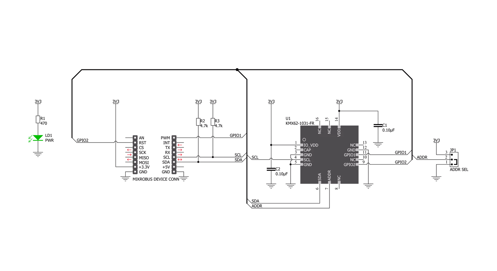
Click board™ Schematic
Step by step
Project assembly

Start by selecting your development board and Click board™. Begin with the Curiosity Nano with PIC18F57Q43 as your development board.


Track your results in real time
Application Output
1. Application Output - In Debug mode, the 'Application Output' window enables real-time data monitoring, offering direct insight into execution results. Ensure proper data display by configuring the environment correctly using the provided tutorial.

2. UART Terminal - Use the UART Terminal to monitor data transmission via a USB to UART converter, allowing direct communication between the Click board™ and your development system. Configure the baud rate and other serial settings according to your project's requirements to ensure proper functionality. For step-by-step setup instructions, refer to the provided tutorial.

3. Plot Output - The Plot feature offers a powerful way to visualize real-time sensor data, enabling trend analysis, debugging, and comparison of multiple data points. To set it up correctly, follow the provided tutorial, which includes a step-by-step example of using the Plot feature to display Click board™ readings. To use the Plot feature in your code, use the function: plot(*insert_graph_name*, variable_name);. This is a general format, and it is up to the user to replace 'insert_graph_name' with the actual graph name and 'variable_name' with the parameter to be displayed.

Software Support
Library Description
This library contains API for 6DOF IMU 10 Click driver.
Key functions:
c6dofimu10_get_accel_axis- This function gets accelerometer axis datac6dofimu10_get_mag_axis- This function gets magnetometer axis data.c6dofimu10_get_temperature- This function gets temperature data.
Open Source
Code example
The complete application code and a ready-to-use project are available through the NECTO Studio Package Manager for direct installation in the NECTO Studio. The application code can also be found on the MIKROE GitHub account.
/*!
 * \file
 * \brief c6DofImu10 Click example
 *
 * # Description
 * This app reads the accelerometer and magnetometer axis data.
 *
 * The demo application is composed of two sections :
 *
 * ## Application Init
 * Initializes device and runs a communication test that reads
 * device id (registry Who_I_AM).
 *
 * ## Application Task
 * Reads the accelerometer and magnetometer axis data.
 * And reads temperature values. All data logs on the USBUART.
 *
 * \author MikroE Team
 *
 */
// ------------------------------------------------------------------- INCLUDES

#include "board.h"
#include "log.h"
#include "c6dofimu10.h"

// ------------------------------------------------------------------ VARIABLES

static c6dofimu10_t c6dofimu10;
static log_t logger;

// ------------------------------------------------------- ADDITIONAL FUNCTIONS

void app_display_axis_data ( c6dofimu10_axis_t *axis )
{
    log_printf( &logger, "* X: %d \r\n", axis->x );

    log_printf( &logger, "* Y: %d \r\n", axis->y );

    log_printf( &logger, "* Z: %d \r\n", axis->z );

    log_printf( &logger, "------------------------\r\n" );
}

void app_display_temp_data ( float temp )
{
    log_printf( &logger, "* Temperature:  %.2f C\r\n", temp );
    log_printf( &logger, "------------------------\r\n" );
}

// ------------------------------------------------------ APPLICATION FUNCTIONS

void application_init ( void )
{
    log_cfg_t log_cfg;
    c6dofimu10_cfg_t cfg;
    uint8_t com_test;

    /**
     * Logger initialization.
     * Default baud rate: 115200
     * Default log level: LOG_LEVEL_DEBUG
     * @note If USB_UART_RX and USB_UART_TX
     * are defined as HAL_PIN_NC, you will
     * need to define them manually for log to work.
     * See @b LOG_MAP_USB_UART macro definition for detailed explanation.
     */
    LOG_MAP_USB_UART( log_cfg );
    log_init( &logger, &log_cfg );
    log_info( &logger, "---- Application Init ----" );

    //  Click initialization.

    c6dofimu10_cfg_setup( &cfg );
    c6DOFIMU10_MAP_MIKROBUS( cfg, MIKROBUS_1 );
    c6dofimu10_init( &c6dofimu10, &cfg );

    // TEST COMMUNICATION
    com_test = c6dofimu10_communication_test( &c6dofimu10 );
    if ( com_test != C6DOFIMU10_DEVICE_OK )
    {
        log_printf( &logger, "-- Device communication ERROR --\r\n" );
        for( ; ; );
    }
    log_printf( &logger, "-- Device communication OK --\r\n" );
    Delay_ms ( 1000 );
    Delay_ms ( 1000 );

    c6dofimu10_default_cfg ( &c6dofimu10 );
    log_printf( &logger, "-- Device configuration --\r\n" );
    Delay_ms ( 500 );
}

void application_task ( void )
{
    c6dofimu10_axis_t accel_axis;
    c6dofimu10_axis_t mag_axis;
    float temperature;

    c6dofimu10_get_accel_axis ( &c6dofimu10, &accel_axis );
    c6dofimu10_get_mag_axis ( &c6dofimu10, &mag_axis );
    temperature = c6dofimu10_get_temperature( &c6dofimu10, C6DOFIMU10_TEMP_FORMAT_CELSIUS );

    log_printf( &logger, "-- Accelerometer axis --\r\n" );
    app_display_axis_data( &accel_axis );

    log_printf( &logger, "-- Magnetometer axis --\r\n" );
    app_display_axis_data( &mag_axis );

    log_printf( &logger, "-- Temperature data --\r\n" );
    app_display_temp_data( temperature );
    log_printf( &logger, "***************************************************************************************\r\n" );
    Delay_ms ( 1000 );
}

int main ( void )
{
    /* Do not remove this line or clock might not be set correctly. */
    #ifdef PREINIT_SUPPORTED
    preinit();
    #endif

    application_init( );

    for ( ; ; )
    {
        application_task( );
    }

    return 0;
}

// ------------------------------------------------------------------------ END
Additional Support
Resources
Category:Motion


