Add wireless connectivity like WiFi and BLE into your projects with Ai-WB2-12F and PIC18F57Q43
Multiprotocol WiFi and Bluetooth module solution supporting IEEE 802.11b/g/n and BLE 5.0 protocol

Published Mar 06, 2024
Click board™
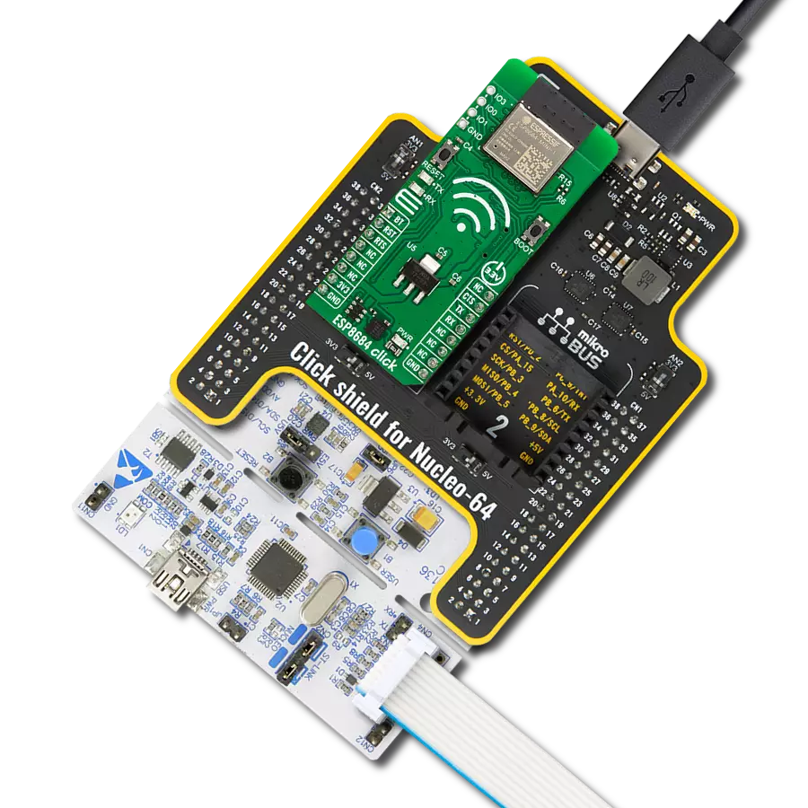
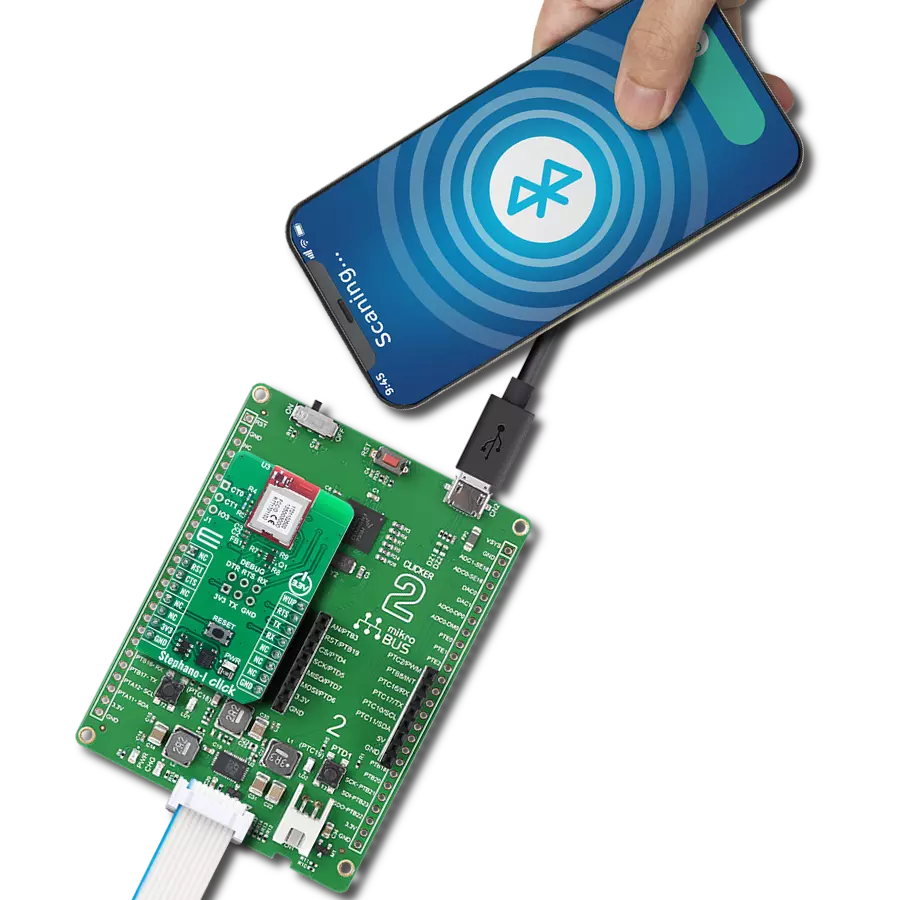
Ai-WB2-12F Click
Dev. board
Curiosity Nano with PIC18F57Q43
Compiler
NECTO Studio
MCU
PIC18F57Q43
Achieve easy integration of wireless WiFi and BLE technologies, along with high-level security and energy efficiency, perfect for developing smart devices and IoT applications
A
A
Hardware Overview
How does it work?
Ai-WB2-12F Click is based on the Ai-WB2-12F, a WiFi and BLE module from Ai-Thinker Technology. At its center lies the BL602 chip, which serves as the primary processor. This chip equips the module with support for WiFi 802.11b/g/n and BLE 5.0 protocols, featuring a low-power 32-bit RISC CPU, 276KB of RAM, and a comprehensive range of peripheral interfaces such as SDIO, SPI, UART, I2C, IR Remote, PWM, ADC, DAC, PIR, and GPIO, among others. Its design is made for extensive application in the Internet of Things (IoT), wearable technology, smart home solutions, and more. In terms of additional specifications, the module boasts an inbuilt PCB antenna covering a frequency range from 2400 to 2483.5MHz, alongside extensive WiFi security protocols, including WPS, WEP, WPA, WPA2 Personal, WPA2 Enterprise, and WPA3. It also supports BLE 5.0
and Bluetooth Mesh, various operational modes such as Station + BLE and Station + SoftAP + BLE, secure boot with ECC-256 signature mirroring, an AES encryption engine for 128/192/256-bit keys, a true random number generator, and a public key accelerator for extensive cryptographic operations. The module facilitates a variety of sleep modes, boasting a deep sleep current of just 12μA, and allows for easy setup with universal AT commands. Moving on to the board's connectivity features, this Click board™ employs a UART interface for communication with the host MCU, using standard UART RX and TX pins to exchange AT commands. By default, it communicates at a baud rate of 115200bps. The Click board™ is additionally equipped with a USB type C connector, enabling direct power supply and configuration via a PC. The board also incorporates a reset feature through the
R5 resistor (disabled by default with unpopulated R5 resistor) connected to the EN pin of the mikroBUS™ socket, an EN button for module enabling, and a PROG button dedicated to firmware programming. An RGB diode serves as a status indicator, signaling the active I/O pin - red for IO14, green for IO17, and blue for IO3. Depending on the user's requirements, these pins are adaptable for various uses such as SPI, PWM, or ADC. The user-configurable I/O pins are not available by default. If you need to use it, please contact Ai-Thinker. This Click board™ can be operated only with a 3.3V logic voltage level. The board must perform appropriate logic voltage level conversion before using MCUs with different logic levels. Also, it comes equipped with a library containing functions and an example code that can be used as a reference for further development.

Features overview
Development board
PIC18F57Q43 Curiosity Nano evaluation kit is a cutting-edge hardware platform designed to evaluate microcontrollers within the PIC18-Q43 family. Central to its design is the inclusion of the powerful PIC18F57Q43 microcontroller (MCU), offering advanced functionalities and robust performance. Key features of this evaluation kit include a yellow user LED and a responsive
mechanical user switch, providing seamless interaction and testing. The provision for a 32.768kHz crystal footprint ensures precision timing capabilities. With an onboard debugger boasting a green power and status LED, programming and debugging become intuitive and efficient. Further enhancing its utility is the Virtual serial port (CDC) and a debug GPIO channel (DGI
GPIO), offering extensive connectivity options. Powered via USB, this kit boasts an adjustable target voltage feature facilitated by the MIC5353 LDO regulator, ensuring stable operation with an output voltage ranging from 1.8V to 5.1V, with a maximum output current of 500mA, subject to ambient temperature and voltage constraints.

Microcontroller Overview
MCU Card / MCU

Architecture
PIC
MCU Memory (KB)
128
Silicon Vendor
Microchip
Pin count
48
RAM (Bytes)
8196
You complete me!
Accessories
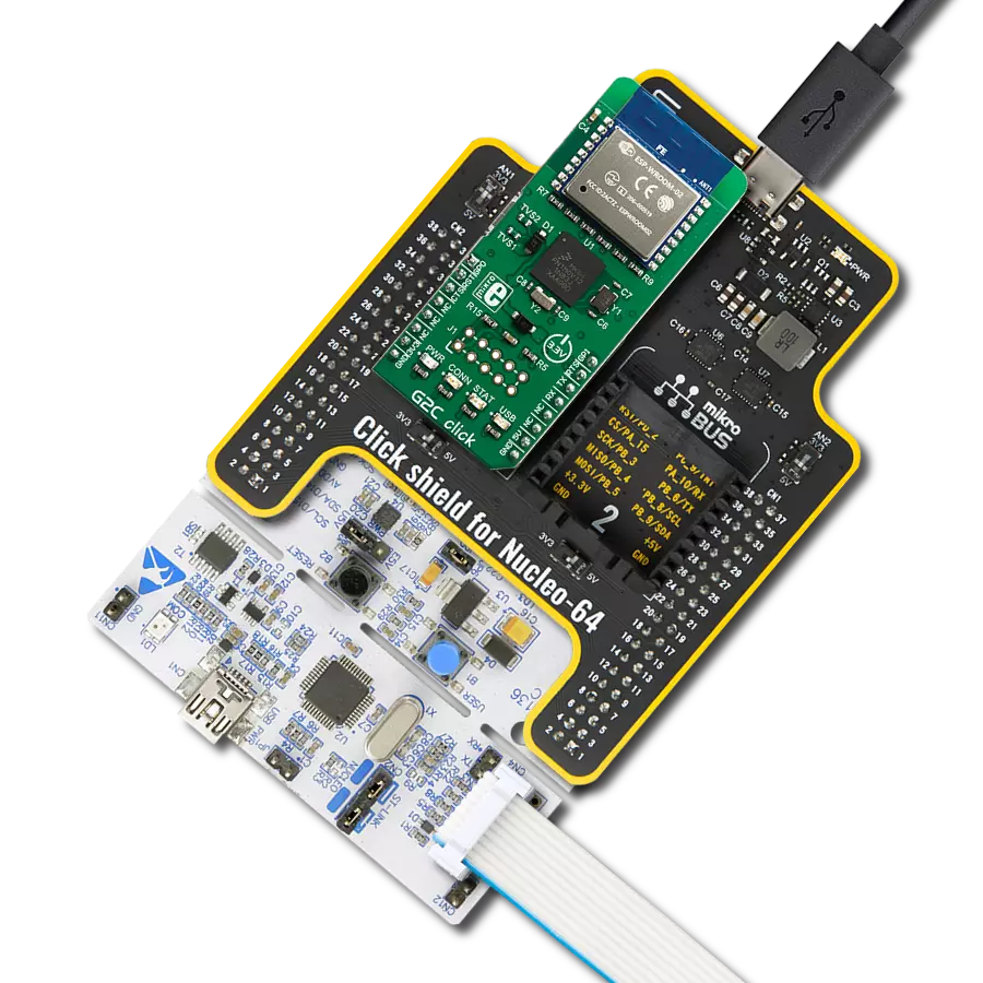
Curiosity Nano Base for Click boards is a versatile hardware extension platform created to streamline the integration between Curiosity Nano kits and extension boards, tailored explicitly for the mikroBUS™-standardized Click boards and Xplained Pro extension boards. This innovative base board (shield) offers seamless connectivity and expansion possibilities, simplifying experimentation and development. Key features include USB power compatibility from the Curiosity Nano kit, alongside an alternative external power input option for enhanced flexibility. The onboard Li-Ion/LiPo charger and management circuit ensure smooth operation for battery-powered applications, simplifying usage and management. Moreover, the base incorporates a fixed 3.3V PSU dedicated to target and mikroBUS™ power rails, alongside a fixed 5.0V boost converter catering to 5V power rails of mikroBUS™ sockets, providing stable power delivery for various connected devices.

Used MCU Pins
mikroBUS™ mapper
Take a closer look
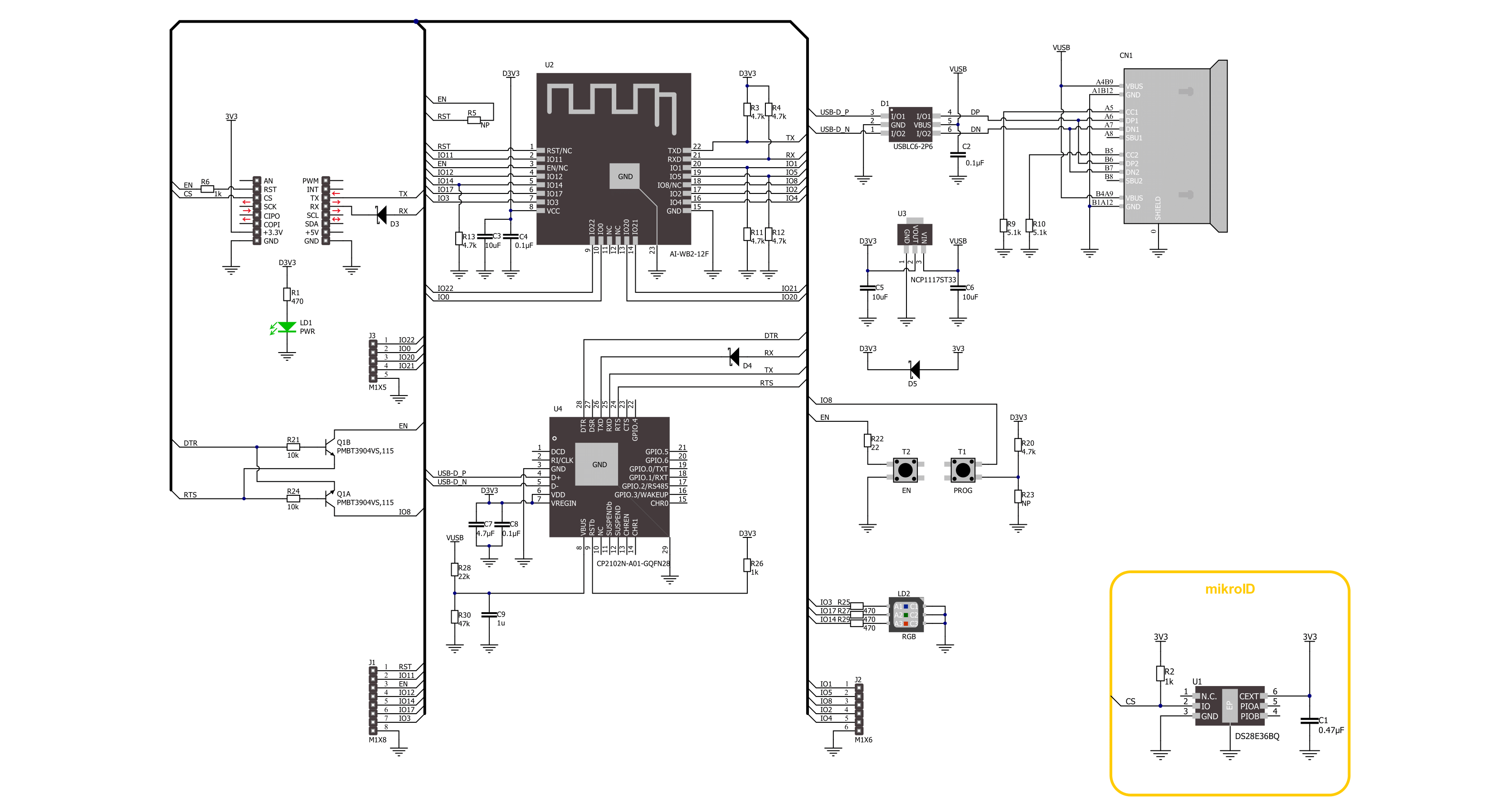
Click board™ Schematic
Step by step
Project assembly

Start by selecting your development board and Click board™. Begin with the Curiosity Nano with PIC18F57Q43 as your development board.


Software Support
Library Description
This library contains API for Ai-WB2-12F Click driver.
Key functions:
aiwb212f_send_cmd- Ai-WB2-12F send command functionaiwb212f_send_cmd_with_par- Ai-WB2-12F send command with parameter functionaiwb212f_send_cmd_check- Ai-WB2-12F send command check function
Open Source
Code example
The complete application code and a ready-to-use project are available through the NECTO Studio Package Manager for direct installation in the NECTO Studio. The application code can also be found on the MIKROE GitHub account.
/*!
 * @file main.c
 * @brief Ai-WB2-12F Click Example.
 *
 * # Description
 * This example demonstrates the use of Ai-WB2-12F Click board by processing
 * the incoming data and displaying them on the USB UART.
 *
 * The demo application is composed of two sections :
 *
 * ## Application Init
 * Initializes the driver, tests the communication, and after that restarts the device, and performs example configuration.
 *
 * ## Application Task
 * Depending on the selected demo example, it sends a TCP/UDP echo server message and receives it or
 * creates BLE Client which receives the messages from the connected device.
 *
 * ## Additional Function
 * - static void aiwb212f_clear_app_buf ( void )
 * - static void aiwb212f_log_app_buf ( void )
 * - static err_t aiwb212f_process ( aiwb212f_t *ctx )
 * - static void aiwb212f_rsp_check ( void )
 * - static void aiwb212f_error_check ( void )
 * - static void aiwb212f_configure_for_example ( void )
 * - static void aiwb212f_example ( void )
 *
 * @note
 * We have used the BLE Scanner Android application for the BLE Example test
 * and you can find it at the link:
 * https://play.google.com/store/apps/details?id=com.macdom.ble.blescanner
 *
 * @author Stefan Ilic
 *
 */

#include "board.h"
#include "log.h"
#include "aiwb212f.h"

// Example selection macros
#define EXAMPLE_TCP_UDP                     0               // Example of sending messages to a TCP/UDP echo server
#define EXAMPLE_BLE                         1               // BLE Example
#define DEMO_EXAMPLE                        EXAMPLE_TCP_UDP // Example selection macro

// Message content
#define MESSAGE_CONTENT                     "Ai-WB2-12F Click board - demo example."
#define MESSAGE_LEN                         "40"

// TCP/UDP example parameters
#define REMOTE_IP                           "77.46.162.162" // TCP/UDP echo server IP address
#define REMOTE_PORT                         "51111"         // TCP/UDP echo server port

// WiFi parameters
#define WIFI_SSID                           "MikroE Public"
#define WIFI_PWD                            "mikroe.guest"

// GPIO parameters
#define LED_RED_GPIO                        "5"
#define LED_GREEN_GPIO                      "6"
#define LED_BLUE_GPIO                       "7"

// Application buffer size
#define APP_BUFFER_SIZE                     200
#define PROCESS_BUFFER_SIZE                 200

static aiwb212f_t aiwb212f;
static log_t logger;
static err_t error_flag;

static uint8_t app_buf[ APP_BUFFER_SIZE ] = { 0 };
static int32_t app_buf_len = 0;

/**
 * @brief Ai-WB2-12F clearing application buffer.
 * @details This function clears memory of application buffer and reset its length.
 * @note None.
 */
static void aiwb212f_clear_app_buf ( void );

/**
 * @brief Ai-WB2-12F log application buffer.
 * @details This function logs data from application buffer to USB UART.
 * @note None.
 */
static void aiwb212f_log_app_buf ( void );

/**
 * @brief Ai-WB2-12F data reading function.
 * @details This function reads data from device and concatenates data to application buffer.
 * @return @li @c  0 - Read some data.
 *         @li @c -1 - Nothing is read.
 * See #err_t definition for detailed explanation.
 * @note None.
 */
static err_t aiwb212f_process ( void );

/**
 * @brief Response check.
 * @details This function checks for response and
 * returns the status of response.
 * @param[in] rsp  Expected response.
 * @return @li @c  0 - OK response.
 *         @li @c -1 - Error response.
 *         @li @c -2 - Timeout error.
 *         @li @c -3 - Unknown error.
 * See #err_t definition for detailed explanation.
 */
static err_t aiwb212f_rsp_check ( uint8_t *rsp );

/**
 * @brief Check for errors.
 * @details This function checks for different types of
 * errors and logs them on UART or logs the response if no errors occured.
 * @param[in] error_flag  Error flag to check.
 */
static void aiwb212f_error_check ( err_t error_flag );

/**
 * @brief Ai-WB2-12F configure for example function.
 * @details This function is used to configure device for example.
 */
static void aiwb212f_configure_for_example ( void );

/**
 * @brief Ai-WB2-12F execute example function.
 * @details This function executes TCP/UDP or BLE example depending on the DEMO_EXAMPLE macro.
 */
static void aiwb212f_example ( void );

void application_init ( void )
{
    log_cfg_t log_cfg;  /**< Logger config object. */
    aiwb212f_cfg_t aiwb212f_cfg;  /**< Click config object. */

    /**
     * Logger initialization.
     * Default baud rate: 115200
     * Default log level: LOG_LEVEL_DEBUG
     * @note If USB_UART_RX and USB_UART_TX
     * are defined as HAL_PIN_NC, you will
     * need to define them manually for log to work.
     * See @b LOG_MAP_USB_UART macro definition for detailed explanation.
     */
    LOG_MAP_USB_UART( log_cfg );
    log_init( &logger, &log_cfg );
    log_info( &logger, " Application Init " );

    // Click initialization.
    aiwb212f_cfg_setup( &aiwb212f_cfg );
    AIWB212F_MAP_MIKROBUS( aiwb212f_cfg, MIKROBUS_1 );
    if ( UART_ERROR == aiwb212f_init( &aiwb212f, &aiwb212f_cfg ) )
    {
        log_error( &logger, " Communication init." );
        for ( ; ; );
    }

    aiwb212f_process( );
    aiwb212f_clear_app_buf( );

    aiwb212f_hw_reset( &aiwb212f );
    error_flag = aiwb212f_rsp_check( AIWB212F_RSP_READY );
    aiwb212f_error_check( error_flag );

    // Check communication
    aiwb212f_send_cmd( &aiwb212f, AIWB212F_CMD_AT );
    error_flag = aiwb212f_rsp_check( AIWB212F_RSP_OK );
    aiwb212f_error_check( error_flag );

    // Restart device
    aiwb212f_send_cmd( &aiwb212f, AIWB212F_CMD_AT_SW_RESET );
    error_flag = aiwb212f_rsp_check( AIWB212F_RSP_READY );
    aiwb212f_error_check( error_flag );

    aiwb212f_configure_for_example( );

    log_info( &logger, " Application Task " );
}

void application_task ( void )
{
    aiwb212f_example( );
}

int main ( void )
{
    /* Do not remove this line or clock might not be set correctly. */
    #ifdef PREINIT_SUPPORTED
    preinit();
    #endif

    application_init( );

    for ( ; ; )
    {
        application_task( );
    }

    return 0;
}

static void aiwb212f_clear_app_buf ( void )
{
    memset( app_buf, 0, app_buf_len );
    app_buf_len = 0;
}

static void aiwb212f_log_app_buf ( void )
{
    for ( int32_t buf_cnt = 0; buf_cnt < app_buf_len; buf_cnt++ )
    {
        log_printf( &logger, "%c", app_buf[ buf_cnt ] );
    }
}

static err_t aiwb212f_process ( void )
{
    uint8_t rx_buf[ PROCESS_BUFFER_SIZE ] = { 0 };
    int32_t overflow_bytes = 0;
    int32_t rx_cnt = 0;
    int32_t rx_size = aiwb212f_generic_read( &aiwb212f, rx_buf, PROCESS_BUFFER_SIZE );
    if ( ( rx_size > 0 ) && ( rx_size <= APP_BUFFER_SIZE ) )
    {
        if ( ( app_buf_len + rx_size ) > APP_BUFFER_SIZE )
        {
            overflow_bytes = ( app_buf_len + rx_size ) - APP_BUFFER_SIZE;
            app_buf_len = APP_BUFFER_SIZE - rx_size;
            memmove ( app_buf, &app_buf[ overflow_bytes ], app_buf_len );
            memset ( &app_buf[ app_buf_len ], 0, overflow_bytes );
        }
        for ( rx_cnt = 0; rx_cnt < rx_size; rx_cnt++ )
        {
            if ( rx_buf[ rx_cnt ] )
            {
                app_buf[ app_buf_len++ ] = rx_buf[ rx_cnt ];
            }
        }
        return AIWB212F_OK;
    }
    return AIWB212F_ERROR;
}

static err_t aiwb212f_rsp_check ( uint8_t *rsp )
{
    uint32_t timeout_cnt = 0;
    uint32_t timeout = 120000;
    aiwb212f_clear_app_buf( );
    aiwb212f_process( );
    while ( ( 0 == strstr( app_buf, rsp ) ) &&
            ( 0 == strstr( app_buf, AIWB212F_RSP_ERROR ) ) )
    {
        aiwb212f_process( );
        if ( timeout_cnt++ > timeout )
        {
            aiwb212f_clear_app_buf( );
            return AIWB212F_ERROR_TIMEOUT;
        }
        Delay_ms ( 1 );
    }
    Delay_ms ( 100 );
    aiwb212f_process( );
    if ( strstr( app_buf, rsp ) )
    {
        return AIWB212F_OK;
    }
    else if ( strstr( app_buf, AIWB212F_RSP_ERROR ) )
    {
        return AIWB212F_ERROR_CMD;
    }
    else
    {
        return AIWB212F_ERROR_UNKNOWN;
    }
}

static void aiwb212f_error_check ( err_t error_flag )
{
    #define LED_STATE_ON        "1"
    #define LED_STATE_OFF       "0"
    uint8_t command_data[ 10 ] = { 0 };

    switch ( error_flag )
    {
        case AIWB212F_OK:
        {
            aiwb212f_log_app_buf( );
            break;
        }
        case AIWB212F_ERROR:
        {
            log_error( &logger, " Overflow!" );

            aiwb212f_set_gpio( &aiwb212f, LED_RED_GPIO, LED_STATE_ON );
            Delay_ms ( 500 );
            aiwb212f_set_gpio( &aiwb212f, LED_RED_GPIO, LED_STATE_OFF );
            break;
        }
        case AIWB212F_ERROR_TIMEOUT:
        {
            log_error( &logger, " Timeout!" );

            aiwb212f_set_gpio( &aiwb212f, LED_RED_GPIO, LED_STATE_ON );
            Delay_ms ( 500 );
            aiwb212f_set_gpio( &aiwb212f, LED_RED_GPIO, LED_STATE_OFF );
            break;
        }
        case AIWB212F_ERROR_CMD:
        {
            log_error( &logger, " CMD!" );

            aiwb212f_set_gpio( &aiwb212f, LED_RED_GPIO, LED_STATE_ON );
            Delay_ms ( 500 );
            aiwb212f_set_gpio( &aiwb212f, LED_RED_GPIO, LED_STATE_OFF );
            break;
        }
        case AIWB212F_ERROR_UNKNOWN:
        default:
        {
            log_error( &logger, " Unknown!" );

            aiwb212f_set_gpio( &aiwb212f, LED_RED_GPIO, LED_STATE_ON );
            Delay_ms ( 500 );
            aiwb212f_set_gpio( &aiwb212f, LED_RED_GPIO, LED_STATE_OFF );
            break;
        }
    }
    log_printf( &logger, "- - - - - - - - - - - - - - - -\r\n" );
    Delay_ms ( 500 );
}

static void aiwb212f_configure_for_example ( void )
{
#if ( EXAMPLE_TCP_UDP == DEMO_EXAMPLE )

    #define WIFI_MODE           "1,0"
    aiwb212f_send_cmd_with_par( &aiwb212f, AIWB212F_CMD_AT_WMODE, WIFI_MODE );
    error_flag = aiwb212f_rsp_check( AIWB212F_RSP_OK );
    aiwb212f_error_check( error_flag );

    // Connect to WiFi
    #define WIFI_CONNECTED      "+EVENT:WIFI_GOT_IP"
    uint8_t wifi_data[ 50 ] = { 0 };
    strcpy( wifi_data, WIFI_SSID );
    strcat( wifi_data, "," );
    strcat( wifi_data, WIFI_PWD );
    aiwb212f_send_cmd_with_par( &aiwb212f, AIWB212F_CMD_AT_WJAP, wifi_data );
    error_flag = aiwb212f_rsp_check( AIWB212F_RSP_OK );
    error_flag = aiwb212f_rsp_check( WIFI_CONNECTED );
    aiwb212f_error_check( error_flag );

#elif ( EXAMPLE_BLE == DEMO_EXAMPLE )

    #define DEVICE_NAME         "Ai-WB2-12F Click"
    aiwb212f_send_cmd_with_par( &aiwb212f, AIWB212F_CMD_AT_BLENAME, DEVICE_NAME );
    error_flag = aiwb212f_rsp_check( AIWB212F_RSP_OK );
    aiwb212f_error_check( error_flag );

    aiwb212f_send_cmd_with_par( &aiwb212f, AIWB212F_CMD_AT_BLEMODE, "0" );
    error_flag = aiwb212f_rsp_check( AIWB212F_RSP_OK );
    aiwb212f_error_check( error_flag );

    #define DEVICE_CONNECT      "+EVENT:BLE_CONNECT"
    log_printf( &logger, "  Please connect your device\r\n" );
    do
    {
        aiwb212f_process();
        aiwb212f_set_gpio( &aiwb212f, LED_BLUE_GPIO, LED_STATE_ON );
        Delay_ms ( 500 );
        aiwb212f_set_gpio( &aiwb212f, LED_BLUE_GPIO, LED_STATE_OFF );
    }
    while ( !strstr( app_buf, DEVICE_CONNECT ) );
    Delay_ms ( 100 );
    aiwb212f_clear_app_buf( );
    log_printf( &logger, "- - - - - - - - - - - - - - - -\r\n" );

#else
    #error "No demo example selected"
#endif
}

static void aiwb212f_example ( void )
{
#if ( EXAMPLE_TCP_UDP == DEMO_EXAMPLE )
    uint8_t command_data[ APP_BUFFER_SIZE ] = { 0 };
    #define TCP_CLIENT          "4"
    #define UDP_CLIENT          "2"
    #define CON_ID              "1"
    #define KEEP_ALIVE          "1"

    aiwb212f_set_gpio( &aiwb212f, LED_BLUE_GPIO, LED_STATE_ON );
    Delay_ms ( 500 );
    aiwb212f_set_gpio( &aiwb212f, LED_BLUE_GPIO, LED_STATE_OFF );

    log_printf( &logger, " TCP Example \r\n" );
    log_printf( &logger, "- - - - - - - - - - - - - - - -\r\n" );

    strcpy( command_data, TCP_CLIENT );
    strcat( command_data, "," );
    strcat( command_data, REMOTE_IP );
    strcat( command_data, "," );
    strcat( command_data, REMOTE_PORT );
    strcat( command_data, "," );
    strcat( command_data, KEEP_ALIVE );
    strcat( command_data, "," );
    strcat( command_data, CON_ID );
    aiwb212f_send_cmd_with_par( &aiwb212f, AIWB212F_CMD_AT_SOCKET, command_data );
    error_flag = aiwb212f_rsp_check( AIWB212F_RSP_OK );
    aiwb212f_error_check( error_flag );

    aiwb212f_send_cmd_check( &aiwb212f, AIWB212F_CMD_AT_SOCKET );
    error_flag = aiwb212f_rsp_check( AIWB212F_RSP_OK );
    aiwb212f_error_check( error_flag );

    strcpy( command_data, CON_ID );
    strcat( command_data, "," );
    strcat( command_data, MESSAGE_LEN );
    strcat( command_data, "," );
    strcat( command_data, MESSAGE_CONTENT );
    aiwb212f_send_cmd_with_par( &aiwb212f, AIWB212F_CMD_AT_SOCKETSENDLINE, command_data );
    error_flag = aiwb212f_rsp_check( AIWB212F_RSP_OK );
    aiwb212f_error_check( error_flag );

    aiwb212f_send_cmd_with_par( &aiwb212f, AIWB212F_CMD_AT_SOCKETREAD, CON_ID );
    error_flag = aiwb212f_rsp_check( AIWB212F_RSP_OK );
    aiwb212f_error_check( error_flag );

    aiwb212f_send_cmd_with_par( &aiwb212f, AIWB212F_CMD_AT_SOCKETDEL, CON_ID );
    error_flag = aiwb212f_rsp_check( AIWB212F_RSP_OK );
    aiwb212f_error_check( error_flag );

    aiwb212f_set_gpio( &aiwb212f, LED_BLUE_GPIO, LED_STATE_ON );
    Delay_ms ( 500 );
    aiwb212f_set_gpio( &aiwb212f, LED_BLUE_GPIO, LED_STATE_OFF );

    // UDP mode doesn't support read function
    log_printf( &logger, " UDP Example \r\n" );
    log_printf( &logger, "- - - - - - - - - - - - - - - -\r\n" );

    strcpy( command_data, UDP_CLIENT );
    strcat( command_data, "," );
    strcat( command_data, REMOTE_IP );
    strcat( command_data, "," );
    strcat( command_data, REMOTE_PORT );
    strcat( command_data, "," );
    strcat( command_data, KEEP_ALIVE );
    strcat( command_data, "," );
    strcat( command_data, CON_ID );
    aiwb212f_send_cmd_with_par( &aiwb212f, AIWB212F_CMD_AT_SOCKET, command_data );
    error_flag = aiwb212f_rsp_check( AIWB212F_RSP_OK );
    aiwb212f_error_check( error_flag );

    aiwb212f_send_cmd_check( &aiwb212f, AIWB212F_CMD_AT_SOCKET );
    error_flag = aiwb212f_rsp_check( AIWB212F_RSP_OK );
    aiwb212f_error_check( error_flag );

    strcpy( command_data, CON_ID );
    strcat( command_data, "," );
    strcat( command_data, MESSAGE_LEN );
    strcat( command_data, "," );
    strcat( command_data, MESSAGE_CONTENT );
    aiwb212f_send_cmd_with_par( &aiwb212f, AIWB212F_CMD_AT_SOCKETSENDLINE, command_data );
    error_flag = aiwb212f_rsp_check( AIWB212F_RSP_OK );
    aiwb212f_error_check( error_flag );

    aiwb212f_send_cmd_with_par( &aiwb212f, AIWB212F_CMD_AT_SOCKETDEL, CON_ID );
    error_flag = aiwb212f_rsp_check( AIWB212F_RSP_OK );
    aiwb212f_error_check( error_flag );
    // 10 seconds delay
    Delay_ms ( 1000 );
    Delay_ms ( 1000 );
    Delay_ms ( 1000 );
    Delay_ms ( 1000 );
    Delay_ms ( 1000 );
    Delay_ms ( 1000 );
    Delay_ms ( 1000 );
    Delay_ms ( 1000 );
    Delay_ms ( 1000 );
    Delay_ms ( 1000 );

#elif ( EXAMPLE_BLE == DEMO_EXAMPLE )
    aiwb212f_process();

    if ( app_buf_len > 0 )
    {
        log_printf( &logger, "%s", app_buf );
        aiwb212f_clear_app_buf(  );
    }

#else
    #error "No demo example selected"
#endif
}

// ------------------------------------------------------------------------ END
Additional Support
Resources
Category:WiFi