Unleash the potential of your BLDC motors with MCP8063 and PIC18F57Q43
Synchronize and conquer with brushless

Published Feb 13, 2024
Click board™
Brushless 4 Click
Dev. board
Curiosity Nano with PIC18F57Q43
Compiler
NECTO Studio
MCU
PIC18F57Q43
Our BLDC solution empowers you to achieve unparalleled motor performance, increasing efficiency and productivity
A
A
Hardware Overview
How does it work?
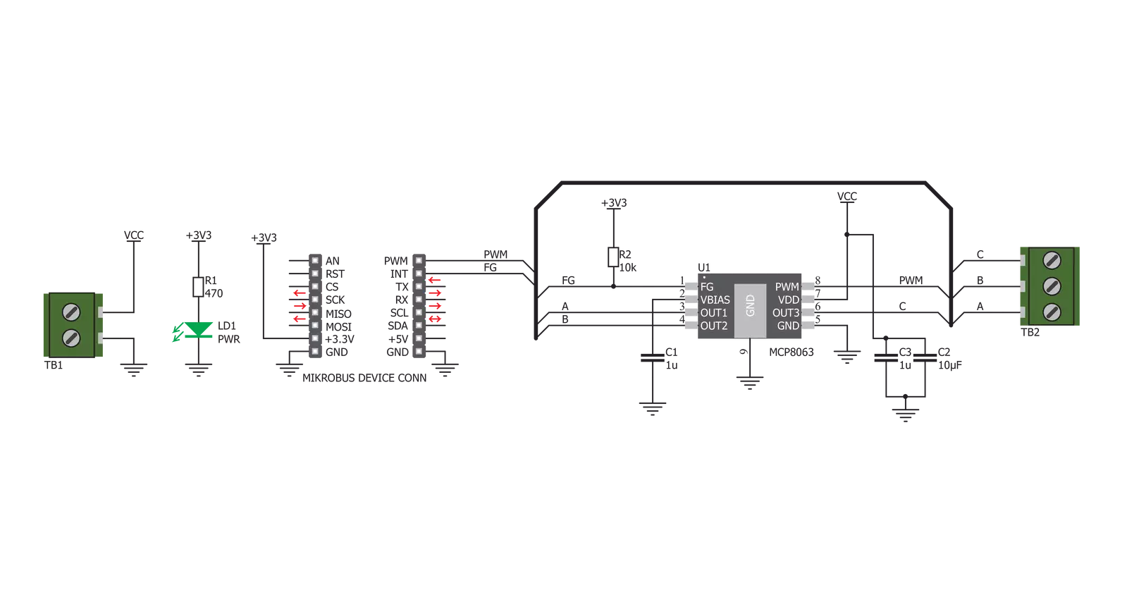
Brushless 4 Click is based on the MCP8063, a 3-phase brushless sinusoidal sensorless motor driver from Microchip. This IC has many features that make it a perfect choice for driving a wide range of small to medium BLDC motors. The MCP8063 requires a low count of external components due to its high degree of integration. It provides the rotor position digital output via the FG pin, routed to the mikroBUS™ INT pin, also labeled as FG on the Click board™ itself. The rotation speed control is implemented via the PWM pin of the mikroBUS™, routed to the PWM input pin of the IC. One of the most distinctive features of the Brushless 4 click is the 180° sinusoidal drive, which provides more torque and better efficiency than the more commonly used 120° driver topology. As mentioned above, the PWM signal can be used to control the motor speed. The duty cycle controls the rotor's speed, while the PWM signal's frequency doesn't affect the rotation speed and can vary between 20 Hz and 100 kHz. When the PWM input is at the HIGH logic level, the motor's rotational speed will be at a maximum. When the PWM input stays at the LOW logic level, the motor is stopped. Toggling between HIGH and LOW logic
states will result in the rotor turning at a specific speed, which depends on the duration of the HIGH logic level state. The PWM pin is routed to the same named pin of the mikroBUS™, conveniently allowing the MCU to provide the required PWM signal. Another method of controlling the motor speed can be implemented by varying the voltage of the motor power supply, which is connected via the input screw terminal, labeled as VBAT. This voltage can range from 2V up to 14V. The power supply has to be connected to the input terminal, as this terminal provides power for both the output stage of the MCP8063, as well as for the internal logic circuit (through the internal voltage regulator). The motor's rotational speed and phase can be determined using the FG pin. This pin acts like the Hall-effect sensor output, providing information about the motor's speed and phase to the host MCU via the mikroBUS™. The FC pin is pulled up with the onboard resistor. When the lock-up or desync condition appears, this pin is set to a high impedance mode, which is pulled to a HIGH logic level - because of the pull-up resistor. When the rotor is blocked, or it loses synchronization, an internal lock-up section
detects this condition and ties the coils to GND, effectively discharging the rotor with minimal self-heating. After a time-out, another attempt is made to run the rotor. If it is still blocked, another lock-up event is detected, and another time-out period is initiated. This way, the rotor is protected from overheating. As already mentioned, the MCP8063 IC features current limit protection. The maximum current is internally limited to 1.5A. This limitation prevents overheating of the motor coils and protects the output stage transistors. A good practice is always keeping the power consumption lower than the maximum specified, ensuring enough overhead. The thermal protection protects the IC when it reaches 170°C, with a hysteresis of 25°C before the restart is attempted, meaning that the IC has to be cooled down to 145°C. The output three-pole screw terminal is used to connect the motor phases. It is labeled with A, B, and C, allowing connecting of the three poles BLDC motors which do not require more than 1.5A (when the internal overcurrent limit is triggered). Brushless 4 Click supports only 3.3V MCUs and is not intended to be connected or controlled via the 5V MCU without proper level shifting circuitry.

Features overview
Development board
PIC18F57Q43 Curiosity Nano evaluation kit is a cutting-edge hardware platform designed to evaluate microcontrollers within the PIC18-Q43 family. Central to its design is the inclusion of the powerful PIC18F57Q43 microcontroller (MCU), offering advanced functionalities and robust performance. Key features of this evaluation kit include a yellow user LED and a responsive
mechanical user switch, providing seamless interaction and testing. The provision for a 32.768kHz crystal footprint ensures precision timing capabilities. With an onboard debugger boasting a green power and status LED, programming and debugging become intuitive and efficient. Further enhancing its utility is the Virtual serial port (CDC) and a debug GPIO channel (DGI
GPIO), offering extensive connectivity options. Powered via USB, this kit boasts an adjustable target voltage feature facilitated by the MIC5353 LDO regulator, ensuring stable operation with an output voltage ranging from 1.8V to 5.1V, with a maximum output current of 500mA, subject to ambient temperature and voltage constraints.

Microcontroller Overview
MCU Card / MCU

Architecture
PIC
MCU Memory (KB)
128
Silicon Vendor
Microchip
Pin count
48
RAM (Bytes)
8196
You complete me!
Accessories
Curiosity Nano Base for Click boards is a versatile hardware extension platform created to streamline the integration between Curiosity Nano kits and extension boards, tailored explicitly for the mikroBUS™-standardized Click boards and Xplained Pro extension boards. This innovative base board (shield) offers seamless connectivity and expansion possibilities, simplifying experimentation and development. Key features include USB power compatibility from the Curiosity Nano kit, alongside an alternative external power input option for enhanced flexibility. The onboard Li-Ion/LiPo charger and management circuit ensure smooth operation for battery-powered applications, simplifying usage and management. Moreover, the base incorporates a fixed 3.3V PSU dedicated to target and mikroBUS™ power rails, alongside a fixed 5.0V boost converter catering to 5V power rails of mikroBUS™ sockets, providing stable power delivery for various connected devices.

Brushless DC (BLDC) Motor with a Hall sensor represents a high-performance motor from the 42BLF motor series. This motor, wired in a star configuration, boasts a Hall Effect angle of 120°, ensuring precise and reliable performance. With a compact motor length of 47mm and a lightweight design tipping the scales at just 0.29kg, this BLDC motor is engineered to meet your needs. Operating flawlessly at a voltage rating of 24VDC and a speed range of 4000 ± 10% RPM, this motor offers consistent and dependable power. It excels in a normal operational temperature range from -20 to +50°C, maintaining efficiency with a rated current of 1.9A. Also, this product seamlessly integrates with all Brushless Click boards™ and those that require BLDC motors with Hall sensors.

Used MCU Pins
mikroBUS™ mapper
Take a closer look
Click board™ Schematic
Step by step
Project assembly

Start by selecting your development board and Click board™. Begin with the Curiosity Nano with PIC18F57Q43 as your development board.


Track your results in real time
Application Output
1. Application Output - In Debug mode, the 'Application Output' window enables real-time data monitoring, offering direct insight into execution results. Ensure proper data display by configuring the environment correctly using the provided tutorial.

2. UART Terminal - Use the UART Terminal to monitor data transmission via a USB to UART converter, allowing direct communication between the Click board™ and your development system. Configure the baud rate and other serial settings according to your project's requirements to ensure proper functionality. For step-by-step setup instructions, refer to the provided tutorial.

3. Plot Output - The Plot feature offers a powerful way to visualize real-time sensor data, enabling trend analysis, debugging, and comparison of multiple data points. To set it up correctly, follow the provided tutorial, which includes a step-by-step example of using the Plot feature to display Click board™ readings. To use the Plot feature in your code, use the function: plot(*insert_graph_name*, variable_name);. This is a general format, and it is up to the user to replace 'insert_graph_name' with the actual graph name and 'variable_name' with the parameter to be displayed.

Software Support
Library Description
This library contains API for Brushless 4 Click driver.
Key functions:
brushless4_set_duty_cycle- This function sets the PWM duty cyclebrushless4_pwm_start- This function starts PWM modulebrushless4_pwm_pin- This function sets the state of the PWM pin
Open Source
Code example
The complete application code and a ready-to-use project are available through the NECTO Studio Package Manager for direct installation in the NECTO Studio. The application code can also be found on the MIKROE GitHub account.
/*!
 * @file
 * @brief Brushless 4 Click example
 *
 * # Description
 * This Click has many features for driving a wide range of small to medium BLDC motors.
 * It provides the rotor position digital output, via the FG pin, routed to the mikroBUS INT pin.
 *
 * The demo application is composed of two sections :
 *
 * ## Application Init
 * Initializes the GPIO driver
 * and configures the PWM peripheral for controlling the speed of the motor.
 *
 * ## Application Task
 * This is an example that demonstrates the use of a Brushless 4 Click board.
 * Brushless 4 Click communicates with the register via the PWM interface.
 * Increases and decreasing the speed of the motor demonstrate speed control.
 * Results are being sent to the Usart Terminal where you can track their changes.
 *
 *
 * @author Nikola Peric
 *
 */
// ------------------------------------------------------------------- INCLUDES

#include "board.h"
#include "log.h"
#include "brushless4.h"

// ------------------------------------------------------------------ VARIABLES

static brushless4_t brushless4;
static log_t logger;

// ------------------------------------------------------ APPLICATION FUNCTIONS

void application_init ( void )
{
    log_cfg_t log_cfg;
    brushless4_cfg_t cfg;

    /**
     * Logger initialization.
     * Default baud rate: 115200
     * Default log level: LOG_LEVEL_DEBUG
     * @note If USB_UART_RX and USB_UART_TX
     * are defined as HAL_PIN_NC, you will
     * need to define them manually for log to work.
     * See @b LOG_MAP_USB_UART macro definition for detailed explanation.
     */
    LOG_MAP_USB_UART( log_cfg );
    log_init( &logger, &log_cfg );
    log_info( &logger, "---- Application Init ----" );

    //  Click initialization.

    brushless4_cfg_setup( &cfg );
    BRUSHLESS4_MAP_MIKROBUS( cfg, MIKROBUS_1 );
    brushless4_init( &brushless4, &cfg );

    brushless4_set_duty_cycle ( &brushless4, 0.0 );
    brushless4_pwm_start( &brushless4 );

    log_info( &logger, "---- Application Task ----" );
    Delay_ms ( 1000 );
}

void application_task ( void )
{
    static int8_t duty_cnt = 1;
    static int8_t duty_inc = 1;
    float duty = duty_cnt / 10.0;

    brushless4_set_duty_cycle ( &brushless4, duty );
    log_printf( &logger, "Duty: %d%%\r\n", ( uint16_t )( duty_cnt * 10 ) );
    Delay_ms ( 500 );

    if ( 10 == duty_cnt )
    {
        duty_inc = -1;
        log_printf( &logger, " Slowing down... \r\n" );
    }
    else if ( 0 == duty_cnt )
    {
        duty_inc = 1;
        log_printf( &logger, " Increasing the motor speed... \r\n" );
    }
    duty_cnt += duty_inc;
}

int main ( void )
{
    /* Do not remove this line or clock might not be set correctly. */
    #ifdef PREINIT_SUPPORTED
    preinit();
    #endif

    application_init( );

    for ( ; ; )
    {
        application_task( );
    }

    return 0;
}


// ------------------------------------------------------------------------ END
Additional Support
Resources
Category:Brushless


