Make BLDC motor spinning as simple as possible with TC78B027FTG and PIC18F57Q43
Unlock the potential of brushless
Published Feb 13, 2024
Click board™
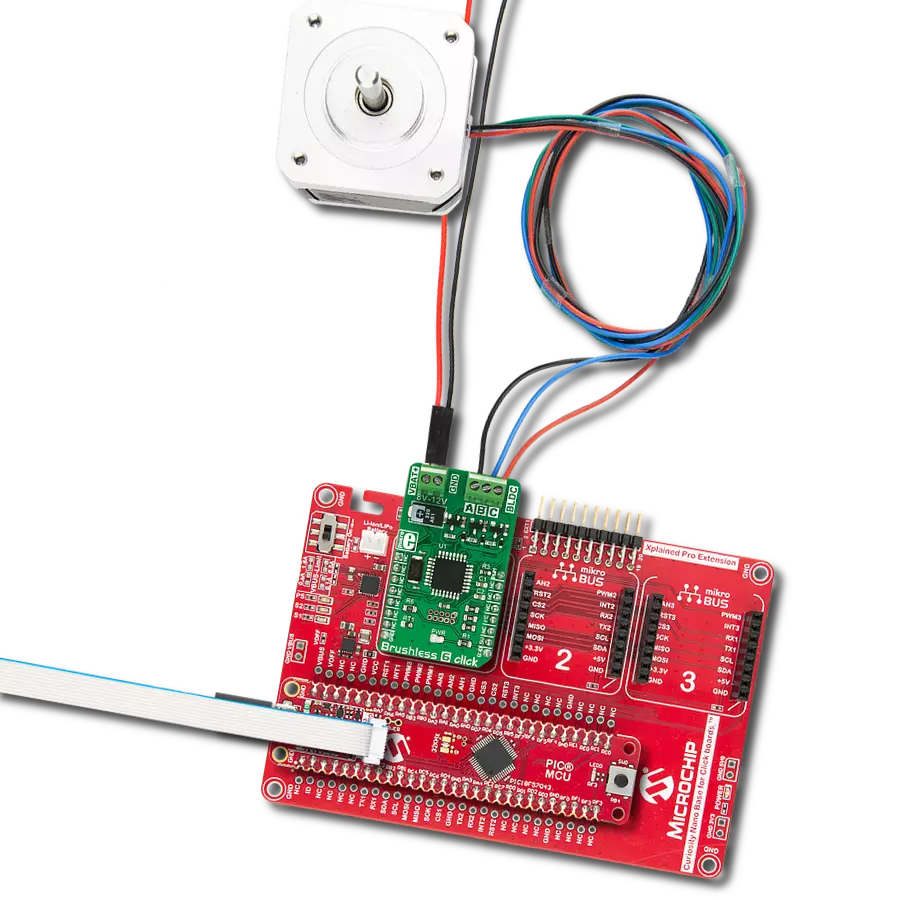
Brushless 9 Click
Dev. board
Curiosity Nano with PIC18F57Q43
Compiler
NECTO Studio
MCU
PIC18F57Q43
Take full command of your motors with our intuitive brushless motor control solution, providing precise speed and torque regulation for optimal performance
A
A
Hardware Overview
How does it work?
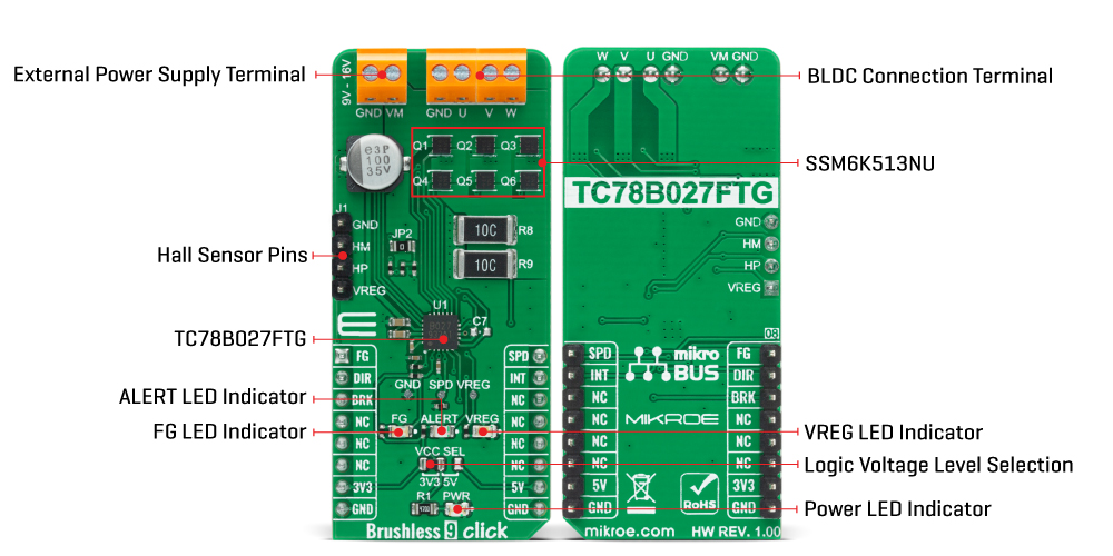
Brushless 9 Click is based on the TC78B027FTG, a 1-Hall sine-wave PWM controller for three-phase brushless DC motors from Toshiba Semiconductor. The TC78B027FTG simplifies the motor selection by using only one Hall sensor input that can be used with either a single Hall sensor motor or the more conventional 3 Hall sensor motors. It can be operated by 1-Hall sine-wave commutation and 1-Hall 150° commutation, which can be switched by register configuration. Also, a closed-loop speed control function is implemented without using an external MCU. The closed-loop control function regulates motor rotational speed fluctuations caused by the power supply voltage and load changes. The TC78B027FTG also has some protection features such as thermal shutdown, overvoltage and overcurrent protection, lock detection, and many more. For Normal operation, it is necessary to apply the voltage from 9V to 16V to the external connector labeled as VM and connect Hall signals from the BLDC motor through the J1 header on the left side of the board. The operation moves to the Standby mode when a
zero cross of the Hall signal is not detected for a lock detection period after the voltage of 1V or less is applied to the SPD pin. In the Standby mode, the power consumption is reduced by powering off its internal 5V regulator. The TC78B027FTG also drives six external N-CH MOSFETs, the SSM6K513NU from Toshiba Semiconductor, that run the connected Brushless DC Motor. For this type of application, more precisely for Brushless Click boards that require BLDC Motor with Hall Sensor for their work, Mikroe offers its users just one such motor, whose offer you can find in our shop. Brushless 9 Click communicates with MCU using several GPIO pins. The DIR pin, routed on the RST pin of the mikroBUS™ socket, is used to select the direction of motor rotation, while the motor braking function is available on the CS pin of the mikroBUS™ socket labeled as BRK. The TC78B027FTG has several braking functions: Motor OFF, Short Brake, Reverse Brake, and Mild Brake. On the other hand, functions such as Motor START, Motor STOP, and Rotation Speed can be set using the SPD pin routed on the PWM pin of the
mikroBUS™ socket, where the register can configure the PWM duty signal and the polarity of this signal. Suppose critical conditions (such over current, over temperature, motor lock) occur. In that case, the TC78B027FTG will signal such a phenomenon using an LED labeled ALERT connected to the interrupt pin marked as INT on the mikroBUS™ socket. Besides, it is possible to detect motor lock events where the indication of such a condition is performed using the LED indicator labeled as FG routed on the AN pin of the mikroBUS™ socket. Pins such as FG, SPD, and INT can also be used as serial interface pins, where FG can be used for SDI or SIO signal, SPD for SCK signal, while INT can be used as SDO signal in case of 3-wire SPI communication. If the SDO line is not used, INT retains its ALERT function. This Click board™ can operate with either 3.3V or 5V logic voltage levels selected via the VCC SEL jumper. This way, both 3.3V and 5V capable MCUs can use the communication lines properly.
Features overview
Development board
PIC18F57Q43 Curiosity Nano evaluation kit is a cutting-edge hardware platform designed to evaluate microcontrollers within the PIC18-Q43 family. Central to its design is the inclusion of the powerful PIC18F57Q43 microcontroller (MCU), offering advanced functionalities and robust performance. Key features of this evaluation kit include a yellow user LED and a responsive
mechanical user switch, providing seamless interaction and testing. The provision for a 32.768kHz crystal footprint ensures precision timing capabilities. With an onboard debugger boasting a green power and status LED, programming and debugging become intuitive and efficient. Further enhancing its utility is the Virtual serial port (CDC) and a debug GPIO channel (DGI
GPIO), offering extensive connectivity options. Powered via USB, this kit boasts an adjustable target voltage feature facilitated by the MIC5353 LDO regulator, ensuring stable operation with an output voltage ranging from 1.8V to 5.1V, with a maximum output current of 500mA, subject to ambient temperature and voltage constraints.

Microcontroller Overview
MCU Card / MCU

Architecture
PIC
MCU Memory (KB)
128
Silicon Vendor
Microchip
Pin count
48
RAM (Bytes)
8196
You complete me!
Accessories
Curiosity Nano Base for Click boards is a versatile hardware extension platform created to streamline the integration between Curiosity Nano kits and extension boards, tailored explicitly for the mikroBUS™-standardized Click boards and Xplained Pro extension boards. This innovative base board (shield) offers seamless connectivity and expansion possibilities, simplifying experimentation and development. Key features include USB power compatibility from the Curiosity Nano kit, alongside an alternative external power input option for enhanced flexibility. The onboard Li-Ion/LiPo charger and management circuit ensure smooth operation for battery-powered applications, simplifying usage and management. Moreover, the base incorporates a fixed 3.3V PSU dedicated to target and mikroBUS™ power rails, alongside a fixed 5.0V boost converter catering to 5V power rails of mikroBUS™ sockets, providing stable power delivery for various connected devices.

Brushless DC (BLDC) Motor with a Hall sensor represents a high-performance motor from the 42BLF motor series. This motor, wired in a star configuration, boasts a Hall Effect angle of 120°, ensuring precise and reliable performance. With a compact motor length of 47mm and a lightweight design tipping the scales at just 0.29kg, this BLDC motor is engineered to meet your needs. Operating flawlessly at a voltage rating of 24VDC and a speed range of 4000 ± 10% RPM, this motor offers consistent and dependable power. It excels in a normal operational temperature range from -20 to +50°C, maintaining efficiency with a rated current of 1.9A. Also, this product seamlessly integrates with all Brushless Click boards™ and those that require BLDC motors with Hall sensors.

Used MCU Pins
mikroBUS™ mapper
Take a closer look
Click board™ Schematic

Step by step
Project assembly

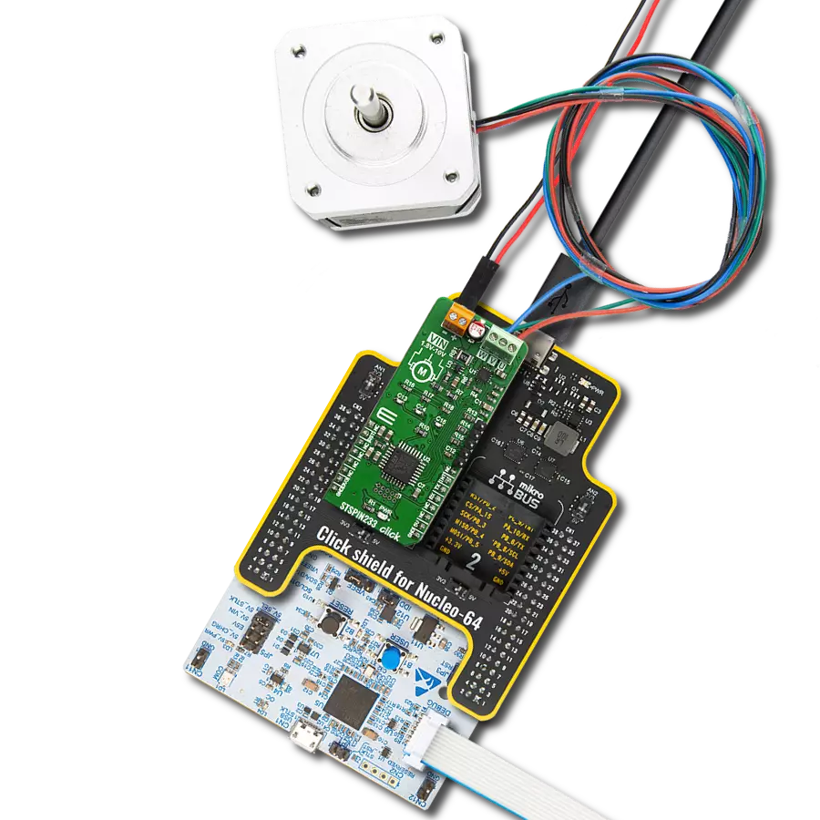
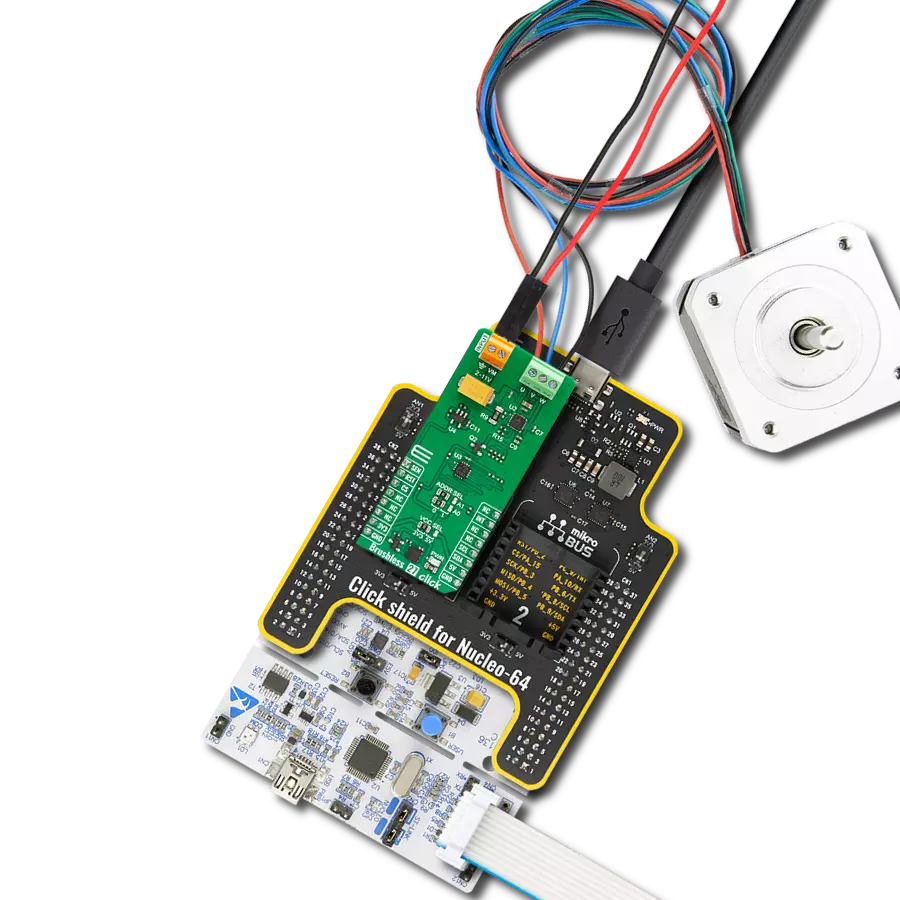
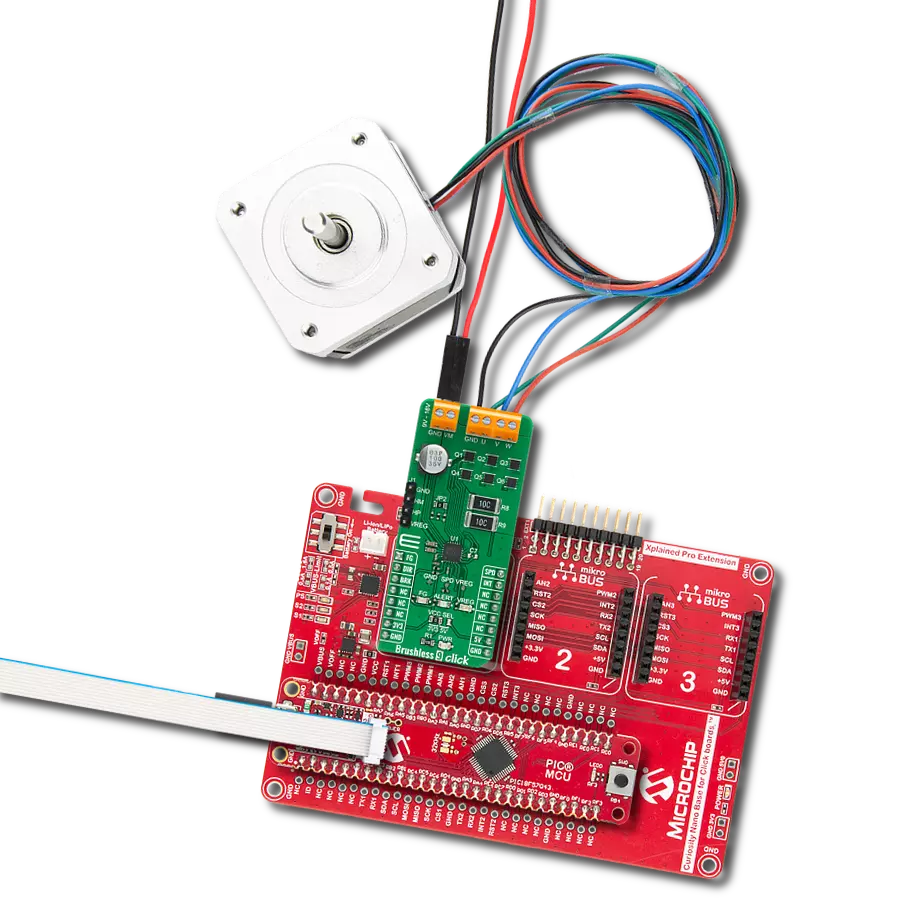
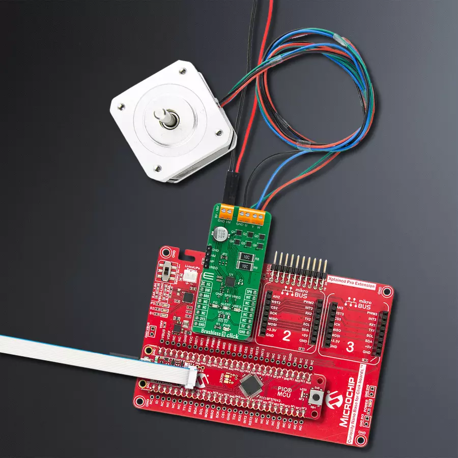
Start by selecting your development board and Click board™. Begin with the Curiosity Nano with PIC18F57Q43 as your development board.


Software Support
Library Description
This library contains API for Brushless 9 Click driver.
Key functions:
brushless9_cfg_setup- This function initializes click configuration structure to initial valuesbrushless9_init- This function initializes all necessary peripheralsbrushless9_default_cfg- This function sets default configuration
Open Source
Code example
The complete application code and a ready-to-use project are available through the NECTO Studio Package Manager for direct installation in the NECTO Studio. The application code can also be found on the MIKROE GitHub account.
/*!
 * @file main.c
 * @brief Brushlesss9 Click example
 *
 * # Description
 * This application is a showcase of controlling speed and direction of brushless motor with hall sensor.
 *
 * The demo application is composed of two sections :
 *
 * ## Application Init
 * Initialization of LOG, PWM module and additional pins for controlling motor.
 *
 * ## Application Task
 * In span of 2 seconds changes duty cycle from 0 to 100% and then back to 0, at the end changes direction of motor.
 *
 * @author Luka Filipovic
 *
 */

#include "board.h"
#include "log.h"
#include "brushless9.h"

#define DUTY_CHANGE_DELAY   2000
#define BREAK_DELAY         5000

static brushless9_t brushless9;
static log_t logger;

static uint8_t direction = 0;

void application_init ( void )
{
    log_cfg_t log_cfg;  /**< Logger config object. */
    brushless9_cfg_t brushless9_cfg;  /**< Click config object. */

    /**
     * Logger initialization.
     * Default baud rate: 115200
     * Default log level: LOG_LEVEL_DEBUG
     * @note If USB_UART_RX and USB_UART_TX
     * are defined as HAL_PIN_NC, you will
     * need to define them manually for log to work.
     * See @b LOG_MAP_USB_UART macro definition for detailed explanation.
     */
    LOG_MAP_USB_UART( log_cfg );
    log_init( &logger, &log_cfg );
    log_info( &logger, " Application Init " );

    // Click initialization.
    brushless9_cfg_setup( &brushless9_cfg );
    BRUSHLESS9_MAP_MIKROBUS( brushless9_cfg, MIKROBUS_1 );
    err_t init_flag  = brushless9_init( &brushless9, &brushless9_cfg );
    if ( init_flag == PWM_ERROR )
    {
        log_error( &logger, " Application Init Error. " );
        log_info( &logger, " Please, run program again... " );

        for ( ; ; );
    }

    brushless9_set_dir( &brushless9, direction );
    brushless9_set_brk( &brushless9, 1 );

    brushless9_set_duty_cycle ( &brushless9, 0 );
    brushless9_pwm_start( &brushless9 );
    log_info( &logger, " Application Task " );
}

void application_task ( void )
{
    log_info( &logger, " Starting... " );
    brushless9_set_brk( &brushless9, 0 );
    for ( uint8_t duty_cnt = 1; duty_cnt < 10; duty_cnt++ )
    {
        Delay_ms ( DUTY_CHANGE_DELAY );
        brushless9_set_duty_cycle ( &brushless9, ( float ) duty_cnt / 10.0 );
        log_printf( &logger, "Duty cycle: %u%%\r\n", ( uint16_t ) ( duty_cnt * 10 ) );
    }

    for ( uint8_t duty_cnt = 10; duty_cnt > 0; duty_cnt-- )
    {
        Delay_ms ( DUTY_CHANGE_DELAY );
        brushless9_set_duty_cycle ( &brushless9, ( float ) duty_cnt / 10.0 );
        log_printf( &logger, "Duty cycle: %u%%\r\n", ( uint16_t ) ( duty_cnt * 10 ) );
    }

    Delay_ms ( DUTY_CHANGE_DELAY );
    log_info( &logger, " Stopping... " );
    brushless9_set_duty_cycle ( &brushless9, 0 );
    brushless9_set_brk( &brushless9, 1 );
    Delay_ms ( BREAK_DELAY );
    log_info( &logger, " Changing direction... " );
    direction = !direction;
    brushless9_set_dir( &brushless9, direction );
}

int main ( void )
{
    /* Do not remove this line or clock might not be set correctly. */
    #ifdef PREINIT_SUPPORTED
    preinit();
    #endif

    application_init( );

    for ( ; ; )
    {
        application_task( );
    }

    return 0;
}

// ------------------------------------------------------------------------ END
Additional Support
Resources
Category:Brushless