Step into a new era of CXPI communication with BD41000AFJ-C and PIC18F57Q43
Transcending communication limits

Published Feb 13, 2024
Click board™
CXPI Click
Dev. board
Curiosity Nano with PIC18F57Q43
Compiler
NECTO Studio
MCU
PIC18F57Q43
Our advanced transceiver seamlessly integrates with CXPI networks, empowering efficient and reliable automotive communication for optimal data exchange in demanding environments
A
A
Hardware Overview
How does it work?
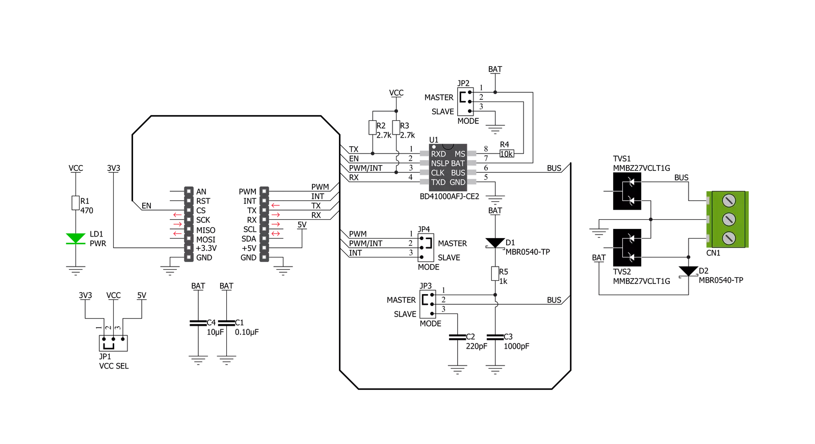
CXPI Click is based on the BD41000AFJ-C, a transceiver for the Clock Extension Peripheral Interface (CXPI) communication from Rohm Semiconductor. The BD41000FJ-C complies with the CXPI standard established by JSAE (Society of Automotive Engineers of Japan), enabling highly responsive, reliable multiplex communication even in HMI systems, reducing vehicle weight and increasing fuel efficiency. The BD41000AFJ-C operates from 7V to 18V external power supply labeled as BAT and has several operating modes, each controlled by the CS pin of the mikroBUS™, BUS pin, and UART TX pin. It has built-in Power-OFF, Through, and RX Through other than CODEC Mode for power-saving control. Power-OFF Mode reduces power consumption by not supplying power to circuits other than necessary for Wake-Up pulse detection (BUS) and Wake-Up input
detection (TX). Through Mode does not process Coding/Decoding. It only directly drives signals from UART TX to BUS and from BUS to UART RX. RX Through Mode reverses RX output at each rising edge of BUS. CODEC Mode is the mode of CXPI communication. CS pin of the mikroBUS™ socket labeled as EN should be set high for the chip to enter CODEC Mode. The BD41000AFJ-C can achieve a quiescent 3uA (typ.) current, ensuring suitability with automotive applications. As a result, the battery load is minimized during non-operation, contributing to higher energy savings. Also, high ESD resistance (±8kV) makes achieving low-power, high-reliability CXPI communication possible. Besides, it has built-in fail-safe functions that suspend the output data upon detecting under-voltage or temperature abnormality. CXPI Click communicates
with MCU using the UART interface with a transmission speed range from 5kbps to 20kbps and commonly used UART RX and TX pins for data transfer. Also, it has three jumpers that allow the selection of CXPI transmitter mode on the MS pin of the BD41000AFJ-C to its appropriate position marked as Master or Slave. This can be performed by using the SMD jumpers labeled as MODE. Note that all the jumpers must be placed on the same side, or the Click board™ may become unresponsive. This Click board™ can operate with either 3.3V or 5V logic voltage levels selected via the VCC SEL jumper. This way, both 3.3V and 5V capable MCUs can use the communication lines properly. Also, this Click board™ comes equipped with a library containing easy-to-use functions and an example code that can be used, as a reference, for further development.

Features overview
Development board
PIC18F57Q43 Curiosity Nano evaluation kit is a cutting-edge hardware platform designed to evaluate microcontrollers within the PIC18-Q43 family. Central to its design is the inclusion of the powerful PIC18F57Q43 microcontroller (MCU), offering advanced functionalities and robust performance. Key features of this evaluation kit include a yellow user LED and a responsive
mechanical user switch, providing seamless interaction and testing. The provision for a 32.768kHz crystal footprint ensures precision timing capabilities. With an onboard debugger boasting a green power and status LED, programming and debugging become intuitive and efficient. Further enhancing its utility is the Virtual serial port (CDC) and a debug GPIO channel (DGI
GPIO), offering extensive connectivity options. Powered via USB, this kit boasts an adjustable target voltage feature facilitated by the MIC5353 LDO regulator, ensuring stable operation with an output voltage ranging from 1.8V to 5.1V, with a maximum output current of 500mA, subject to ambient temperature and voltage constraints.

Microcontroller Overview
MCU Card / MCU

Architecture
PIC
MCU Memory (KB)
128
Silicon Vendor
Microchip
Pin count
48
RAM (Bytes)
8196
You complete me!
Accessories
Curiosity Nano Base for Click boards is a versatile hardware extension platform created to streamline the integration between Curiosity Nano kits and extension boards, tailored explicitly for the mikroBUS™-standardized Click boards and Xplained Pro extension boards. This innovative base board (shield) offers seamless connectivity and expansion possibilities, simplifying experimentation and development. Key features include USB power compatibility from the Curiosity Nano kit, alongside an alternative external power input option for enhanced flexibility. The onboard Li-Ion/LiPo charger and management circuit ensure smooth operation for battery-powered applications, simplifying usage and management. Moreover, the base incorporates a fixed 3.3V PSU dedicated to target and mikroBUS™ power rails, alongside a fixed 5.0V boost converter catering to 5V power rails of mikroBUS™ sockets, providing stable power delivery for various connected devices.

Used MCU Pins
mikroBUS™ mapper
Take a closer look
Click board™ Schematic
Step by step
Project assembly

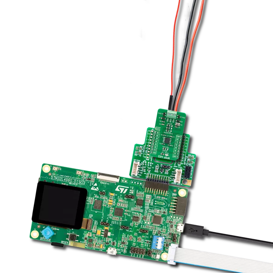
Start by selecting your development board and Click board™. Begin with the Curiosity Nano with PIC18F57Q43 as your development board.


Software Support
Library Description
This library contains API for CXPI Click driver.
Key functions:
cxpi_send_command- Send commandcxpi_set_pwm_pin_state- Set PWM pin state functioncxpi_set_through_mode- Set through mode function.
Open Source
Code example
The complete application code and a ready-to-use project are available through the NECTO Studio Package Manager for direct installation in the NECTO Studio. The application code can also be found on the MIKROE GitHub account.
/*!
 * @file main.c
 * @brief CXPI Click Example.
 *
 * # Description
 * This is an example that demonstrates the use of the CXPI Click board.
 *
 * The demo application is composed of two sections :
 *
 * ## Application Init
 * Initializes UART driver.
 * In addition to this module is placed inside transmitter/receiver working mode
 * cappable of transmission/receive the data.
 *
 * ## Application Task
 * Transmitter/Receiver task depend on uncommented code
 * Receiver logging each received byte to the UART for data logging,
 * while transmitted send messages every 5 seconds.
 *
 * ## Additional Function
 * - static void cxpi_clear_current_rsp_buf ( void )
 * - static void cxpi_process ( void )
 *
 * @author Stefan Ilic
 *
 */

#include "board.h"
#include "log.h"
#include "cxpi.h"

#define PROCESS_COUNTER 10
#define PROCESS_RX_BUFFER_SIZE 100
#define PROCESS_PARSER_BUFFER_SIZE 100

//#define DEMO_APP_RECEIVER
#define DEMO_APP_TRANSMITTER

static cxpi_t cxpi;
static log_t logger;

static char current_rsp_buf[ PROCESS_PARSER_BUFFER_SIZE ];
unsigned char demo_message[ 9 ] = { 'M', 'i', 'k', 'r', 'o', 'E', 13, 10, 0 };

/**
 * @brief CXPI clearing application buffer.
 * @details This function clears memory of application buffer and resets it's length and counter.
 */
static void cxpi_clear_current_rsp_buf ( void );

/**
 * @brief CXPI data reading function.
 * @details This function reads data from device and concatenates data to application buffer.
 */
static void cxpi_process ( void );

void application_init ( void ) {
    log_cfg_t log_cfg;  /**< Logger config object. */
    cxpi_cfg_t cxpi_cfg;  /**< Click config object. */

    /**
     * Logger initialization.
     * Default baud rate: 115200
     * Default log level: LOG_LEVEL_DEBUG
     * @note If USB_UART_RX and USB_UART_TX
     * are defined as HAL_PIN_NC, you will
     * need to define them manually for log to work.
     * See @b LOG_MAP_USB_UART macro definition for detailed explanation.
     */
    LOG_MAP_USB_UART( log_cfg );
    log_init( &logger, &log_cfg );

    // Click initialization.

    cxpi_cfg_setup( &cxpi_cfg );
    CXPI_MAP_MIKROBUS( cxpi_cfg, MIKROBUS_1 );
    err_t init_flag  = cxpi_init( &cxpi, &cxpi_cfg );
    if ( UART_ERROR == init_flag ) {
        log_error( &logger, " Application Init Error. " );
        log_info( &logger, " Please, run program again... " );

        for ( ; ; );
    }
    log_info( &logger, " Application Task " );
    cxpi_set_through_mode( &cxpi );

#ifdef DEMO_APP_TRANSMITTER
    log_printf( &logger, "------------------\r\n" );
    log_printf( &logger, "    Send data:    \r\n" );
    log_printf( &logger, "      MikroE      \r\n" );
    Delay_ms ( 1000 );
#elif defined DEMO_APP_RECEIVER
    log_printf( &logger, "------------------\r\n" );
    log_printf( &logger, "   Receive data  \r\n" );
    Delay_ms ( 1000 );
    Delay_ms ( 1000 );
#else
    # error PLEASE SELECT TRANSMIT OR RECEIVE MODE!!!
#endif

    log_printf( &logger, "------------------\r\n" );
}

void application_task ( void ) {
#ifdef DEMO_APP_TRANSMITTER
    cxpi_send_command( &cxpi, &demo_message[ 0 ] );
    log_printf( &logger, " Sent data : %s",  &demo_message[ 0 ] );
    log_printf( &logger, "------------------\r\n" );
    Delay_ms ( 1000 );
    Delay_ms ( 1000 );
    Delay_ms ( 1000 );
    Delay_ms ( 1000 );
    Delay_ms ( 1000 );
#elif defined DEMO_APP_RECEIVER
    cxpi_process( );
    if ( current_rsp_buf > 0 ) {
        log_printf( &logger, "%s", current_rsp_buf );
        cxpi_clear_current_rsp_buf( );
    }
#else
    # error PLEASE SELECT TRANSMIT OR RECEIVE MODE!!!
#endif
}

int main ( void )
{
    /* Do not remove this line or clock might not be set correctly. */
    #ifdef PREINIT_SUPPORTED
    preinit();
    #endif

    application_init( );

    for ( ; ; )
    {
        application_task( );
    }

    return 0;
}

static void cxpi_clear_current_rsp_buf ( void ) {
    memset( current_rsp_buf, 0, PROCESS_PARSER_BUFFER_SIZE );
}

static void cxpi_process ( void ) {
    int16_t rsp_size;
    uint16_t rsp_cnt = 0;

    char uart_rx_buffer[ PROCESS_RX_BUFFER_SIZE ] = { 0 };
    uint8_t check_buf_cnt;
    uint8_t process_cnt = PROCESS_COUNTER;

    // Clear parser buffer
    memset( current_rsp_buf, 0 , PROCESS_PARSER_BUFFER_SIZE );

    while( process_cnt != 0 ) {
        rsp_size = cxpi_generic_read( &cxpi, &uart_rx_buffer, PROCESS_RX_BUFFER_SIZE );

        if ( rsp_size > 0 ) {
            // Validation of the received data
            for ( check_buf_cnt = 0; check_buf_cnt < rsp_size; check_buf_cnt++ ) {
                if ( uart_rx_buffer[ check_buf_cnt ] == 0 ) {
                    uart_rx_buffer[ check_buf_cnt ] = 13;
                }
            }
            // Storages data in parser buffer
            rsp_cnt += rsp_size;
            if ( rsp_cnt < PROCESS_PARSER_BUFFER_SIZE ) {
                strncat( current_rsp_buf, uart_rx_buffer, rsp_size );
            }

            // Clear RX buffer
            memset( uart_rx_buffer, 0, PROCESS_RX_BUFFER_SIZE );
        } else {
            process_cnt--;
            // Process delay
            Delay_ms ( 100 );
        }
    }
}

// ------------------------------------------------------------------------ END
Additional Support
Resources
Category:CXPI