Deliver data and control signals where you need them most thanks to the MAX41460 and PIC18F57Q43
Transmitting excellence, everywhere.

Published Feb 13, 2024
Click board™
ISM TX Click
Dev. board
Curiosity Nano with PIC18F57Q43
Compiler
NECTO Studio
MCU
PIC18F57Q43
Our ISM RF transmitter solution ensures excellence in wireless data transmission across a spectrum of industries, from IoT to remote monitoring.
A
A
Hardware Overview
How does it work?
ISM TX Click is based on the MAX41460, a UHF sub-GHz ISM/SRD transmitter designed to transmit On-Off Keying (OOK), Amplitude- Shift Keying (ASK), Frequency-Shift Keying (FSK), and Gaussian (G)FSK (or 2GFSK) data from Analog Devices. The crystal-based architecture of the MAX41460 provides greater modulation depth, faster frequency settling, higher tolerance of the transmit frequency, and reduced temperature dependence. It integrates a fractional phase-locked loop (PLL), so a single, low-cost crystal of 16MHz used on this Click board™ can generate commonly used worldwide sub-GHz frequencies. A buffered clock-out signal makes the device compatible with almost any MCU or code-hopping generator. The MAX41460 features a fast oscillator Wake-Up upon data activity detection and has an Auto-Shutdown feature to extend battery life. This Click board™ has four major operating states: Shutdown, Stand-By, Programming, and Transmitter-Enabled Mode.
These states describe the Power-ON/Power-OFF status of the transmitter's three primary internal circuit blocks: the crystal oscillator (XO), the PLL synthesizer, and a high-efficiency, open-drain switching-mode power amplifier (PA). To ensure the MAX41460 enters the shutdown state after Power-On, the DATA pin must be held low at Power-On. The PA pin is used to adjust the frequency with only frequency-dependent components required for the external antenna-matching network that are connected so that the frequency of this Click board™ is fixed to 433.92MHz. The MAX41460 communicates with MCU using the standard SPI serial interface with a maximum frequency of 20 MHz. The device can support two types of SPI transactions: register access only and register access, followed by data transmission. In both Shutdown and Stand-By states, programming through the SPI interface is not allowed. Configuration register values are retained in all
states unless changed by programming or if the device is powered off. This Click board™, alongside the power LED indicator, has an additional green LED indicator labeled as DATA used to visually indicate the successful transmission of data across the SPI interface. ISM TX Click possesses the SMA antenna connector, and it can be used for connecting the appropriate antenna that MIKROE has in its offer, such as Rubber Antenna GSM/GPRS Right Angle. This antenna is an excellent choice for all GSM/GPRS applications and supports a range of frequencies and bands. This Click board™ can be operated only with a 3.3V logic voltage level. The board must perform appropriate logic voltage level conversion before using MCUs with different logic levels. Also, it comes equipped with a library containing functions and an example code that can be used as a reference for further development.

Features overview
Development board
PIC18F57Q43 Curiosity Nano evaluation kit is a cutting-edge hardware platform designed to evaluate microcontrollers within the PIC18-Q43 family. Central to its design is the inclusion of the powerful PIC18F57Q43 microcontroller (MCU), offering advanced functionalities and robust performance. Key features of this evaluation kit include a yellow user LED and a responsive
mechanical user switch, providing seamless interaction and testing. The provision for a 32.768kHz crystal footprint ensures precision timing capabilities. With an onboard debugger boasting a green power and status LED, programming and debugging become intuitive and efficient. Further enhancing its utility is the Virtual serial port (CDC) and a debug GPIO channel (DGI
GPIO), offering extensive connectivity options. Powered via USB, this kit boasts an adjustable target voltage feature facilitated by the MIC5353 LDO regulator, ensuring stable operation with an output voltage ranging from 1.8V to 5.1V, with a maximum output current of 500mA, subject to ambient temperature and voltage constraints.

Microcontroller Overview
MCU Card / MCU

Architecture
PIC
MCU Memory (KB)
128
Silicon Vendor
Microchip
Pin count
48
RAM (Bytes)
8196
You complete me!
Accessories
Curiosity Nano Base for Click boards is a versatile hardware extension platform created to streamline the integration between Curiosity Nano kits and extension boards, tailored explicitly for the mikroBUS™-standardized Click boards and Xplained Pro extension boards. This innovative base board (shield) offers seamless connectivity and expansion possibilities, simplifying experimentation and development. Key features include USB power compatibility from the Curiosity Nano kit, alongside an alternative external power input option for enhanced flexibility. The onboard Li-Ion/LiPo charger and management circuit ensure smooth operation for battery-powered applications, simplifying usage and management. Moreover, the base incorporates a fixed 3.3V PSU dedicated to target and mikroBUS™ power rails, alongside a fixed 5.0V boost converter catering to 5V power rails of mikroBUS™ sockets, providing stable power delivery for various connected devices.

Right angle 433MHz rubber antenna boasts a frequency range of 433MHz, ensuring optimal performance within this spectrum. With a 50Ohm impedance, it facilitates efficient signal transmission. The antenna's vertical polarization enhances signal reception in a specific orientation. Featuring a 1.5dB gain, it can improve signal strength to some extent. The antenna can handle a maximum input power of 50W, making it suitable for various applications. Its compact 50mm length minimizes spatial requirements. Equipped with an SMA male connector, it easily interfaces with compatible devices. This antenna is an adaptable solution for wireless communication needs, particularly when vertical polarization is crucial.

868MHz right-angle rubber antenna is a compact and versatile solution for wireless communication. Operating within the frequency range of 868-915MHz, it ensures optimal signal reception and transmission. With a 50-ohm impedance, it's compatible with various devices and systems. This antenna boasts a 2dB gain, enhancing signal strength and extending communication range. Its vertical polarization further contributes to signal clarity. Designed to handle up to 50W of input power, it's a robust choice for various applications. Measuring just 48mm in length, this antenna is both discreet and practical. Its SMA male connector ensures a secure and reliable connection to your equipment. Whether you're working with IoT devices, remote sensors, or other wireless technologies, the 868MHz right-angle antenna offers the performance and flexibility you need for seamless communication.

Used MCU Pins
mikroBUS™ mapper
Take a closer look
Click board™ Schematic

Step by step
Project assembly

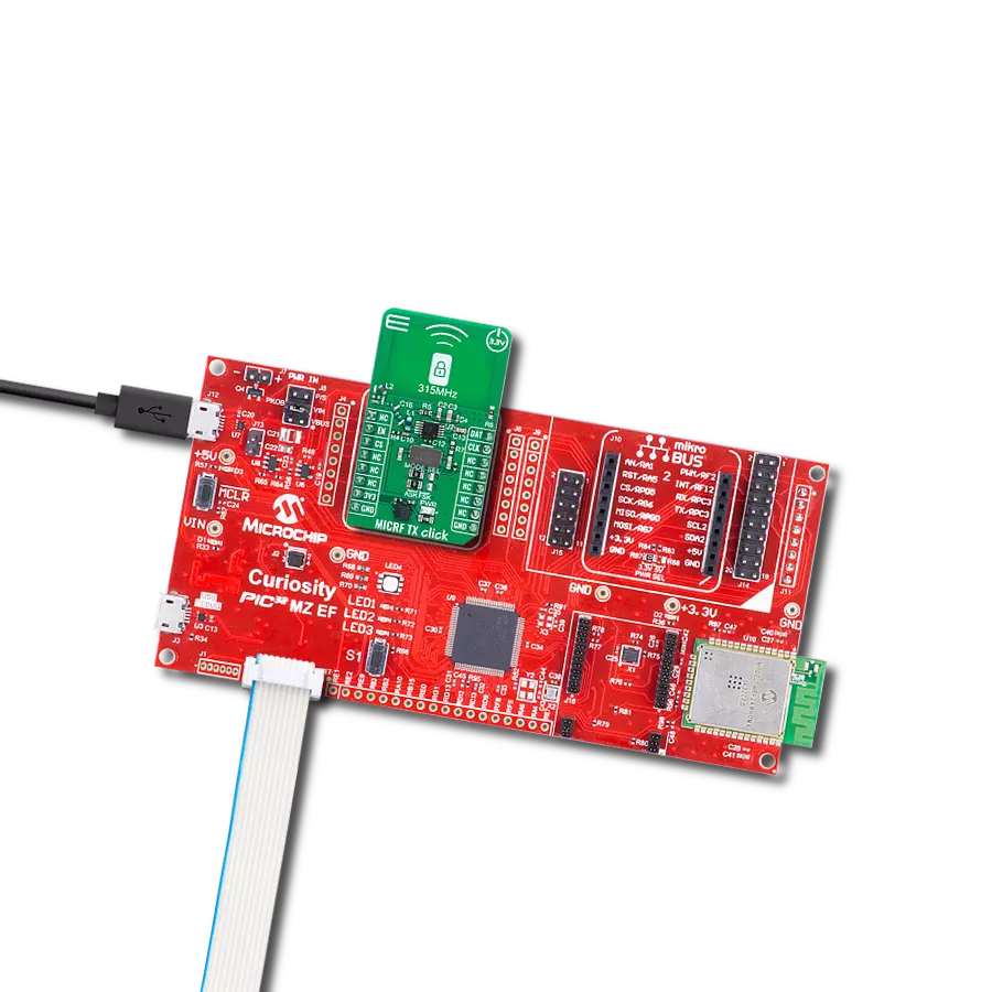
Start by selecting your development board and Click board™. Begin with the Curiosity Nano with PIC18F57Q43 as your development board.


Software Support
Library Description
This library contains API for ISM TX Click driver.
Key functions:
ismtx_set_cfg- ISM TX writing configuration.ismtx_set_frequency- Setting specific frequency for transmission.ismtx_transmit_data- Function for transmitting data with preamble byte and lenght.
Open Source
Code example
The complete application code and a ready-to-use project are available through the NECTO Studio Package Manager for direct installation in the NECTO Studio. The application code can also be found on the MIKROE GitHub account.
/*!
 * @file main.c
 * @brief ISMTX Click example
 *
 * # Description
 * This application shows capability of ISM TX Click board.
 * It sets default configuration, and transmits data in
 * manchester encoding with FSK or ASK signal modulation.
 *
 * The demo application is composed of two sections :
 *
 * ## Application Init
 * Initialization of log and communication, sets signal modulation,
 * resets device, and sets default configuration for selected modulation.
 *
 * ## Application Task
 * Transmits data via external antenna in span of 100ms.
 *
 * @note
 * Default configuration configures device and sets transmission frequency to 433.92 MHz.
 * If selected modulation is FSK frequency deviation is set to 40kHz.
 *
 * @author Luka Filipovic
 *
 */

#include "board.h"
#include "log.h"
#include "ismtx.h"

#define PREAMBLE_BYTE   0xFF

uint8_t tx_data_buf[ 9 ] = { 'M', 'I', 'K', 'R', 'O', 'E', '\r', '\n', 0 };

static ismtx_t ismtx;
static log_t logger;

void application_init ( void )
{
    log_cfg_t log_cfg;      /**< Logger config object. */
    ismtx_cfg_t ismtx_cfg;  /**< Click config object. */

    /**
     * Logger initialization.
     * Default baud rate: 115200
     * Default log level: LOG_LEVEL_DEBUG
     * @note If USB_UART_RX and USB_UART_TX
     * are defined as HAL_PIN_NC, you will
     * need to define them manually for log to work.
     * See @b LOG_MAP_USB_UART macro definition for detailed explanation.
     */
    LOG_MAP_USB_UART( log_cfg );
    log_init( &logger, &log_cfg );
    log_info( &logger, " Application Init " );

    // Click initialization.
    ismtx_cfg_setup( &ismtx_cfg );
    ISMTX_MAP_MIKROBUS( ismtx_cfg, MIKROBUS_1 );
    if ( SPI_MASTER_ERROR == ismtx_init( &ismtx, &ismtx_cfg ) )
    {
        log_error( &logger, " Application Init Error. " );
        log_info( &logger, " Please, run program again... " );
        for ( ; ; );
    }

    ismtx.modulation = ISM_TX_MODULATION_FSK;

    ismtx_soft_reset( &ismtx );

    if ( ismtx_default_cfg ( &ismtx ) < 0 )
    {
        log_error( &logger, " Application Init Error. " );
        log_info( &logger, " Please, select correct signal modulation... " );
        for ( ; ; );
    }

    log_info( &logger, " Application Task " );
}

void application_task ( void )
{
    log_info( &logger, " Data sent: %s", tx_data_buf );
    ismtx_transmit_data( &ismtx, PREAMBLE_BYTE, tx_data_buf, sizeof( tx_data_buf ) );
    Delay_ms ( 100 );
}

int main ( void )
{
    /* Do not remove this line or clock might not be set correctly. */
    #ifdef PREINIT_SUPPORTED
    preinit();
    #endif

    application_init( );

    for ( ; ; )
    {
        application_task( );
    }

    return 0;
}

// ------------------------------------------------------------------------ END
Additional Support
Resources
Category:Sub-1 GHz Transceievers