Create contactless access control systems with ST25DV16K and PIC18F57Q43
NFC Extend: Your tags, your way, with endless antenna possibilities

Published Feb 13, 2024
Click board™
NFC Extend Click
Dev. board
Curiosity Nano with PIC18F57Q43
Compiler
NECTO Studio
MCU
PIC18F57Q43
With NFC Extend, you have the power to shape your NFC experience with custom antennas, allowing you to personalize and adapt your tags to fit unique requirements
A
A
Hardware Overview
How does it work?
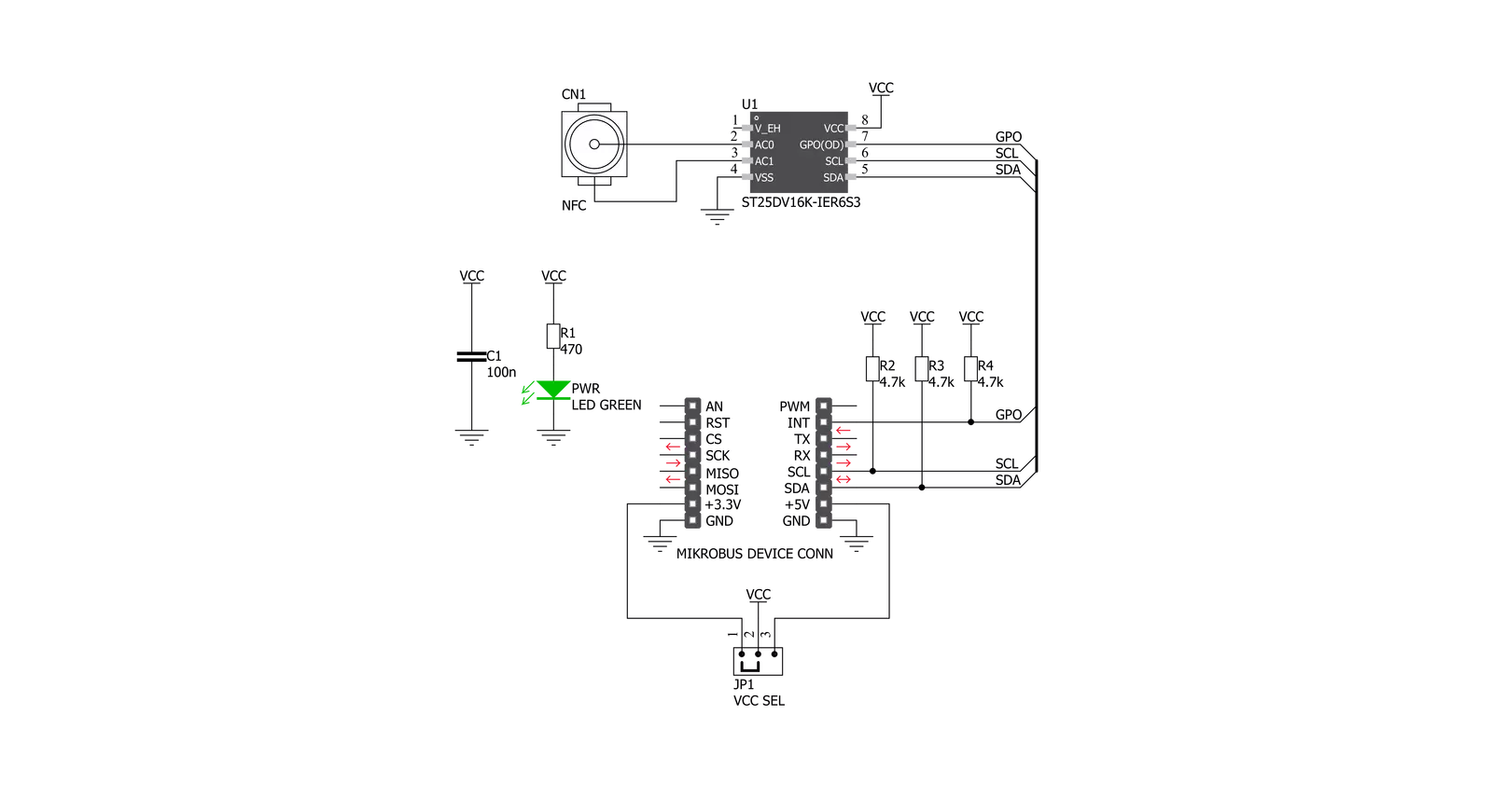
NFC Extend Click is based on the ST25DV16K, a compact NFC tag IC from STMicroelectronics. The Click board™ itself has a reasonably small number of components because most of the interface and EEPROM memory circuitry is already integrated on the ST25DV16K IC. The I2C / SMBus compatible serial interface lines, along with the GPO pin, which also works in the open drain configuration, are pulled up by the on-board resistors. The 2-Wire lines are routed to the respective I2C lines of the mikroBUS™ (SCK and SDA), while the GPO pin of the main IC is routed to the INT pin of the mikroBUS™. Depending on the application requirements various shapes and sizes of 13.56 MHz external antenna can be used by connecting them to CN1 (male U.FL) connector. This Click can utilize new antennas that we have recently
released. The ST25DV16K uses the I2C/SMBus compatible communication interface, offering a fast transfer mode (FTM), to achieve a fast link between RF and contact worlds, via a 256 byte buffer called Mailbox. This mailbox dynamic buffer of 256 byte can be filled or emptied via either RF or I2C. There is also the INT pin available, which indicates incoming event to the contact side, like RF Field changes, RF activity in progress, RF writing completion or Mailbox message availability. The built in energy harvesting element can deliver µW of power when external conditions make it possible. The integrated RF management allows the NFC Extend Click to ignore RF requests. All these features can be programmed by setting static and/or dynamic registers of the ST25DV16K. The ST25DV16K can be partially customized
using configuration registers located in the E2 system area. More information about all the registers can be found in the ST25DV16K datasheet. However, provided library contains functions that simplify the use of the NFC Extend Click. The included application example demonstrates their functionality and it can be used as a reference for custom design. This Click board™ can operate with either 3.3V or 5V logic voltage levels selected via the VCC SEL jumper. This way, both 3.3V and 5V capable MCUs can use the communication lines properly. Also, this Click board™ comes equipped with a library containing easy-to-use functions and an example code that can be used as a reference for further development.


Features overview
Development board
PIC18F57Q43 Curiosity Nano evaluation kit is a cutting-edge hardware platform designed to evaluate microcontrollers within the PIC18-Q43 family. Central to its design is the inclusion of the powerful PIC18F57Q43 microcontroller (MCU), offering advanced functionalities and robust performance. Key features of this evaluation kit include a yellow user LED and a responsive
mechanical user switch, providing seamless interaction and testing. The provision for a 32.768kHz crystal footprint ensures precision timing capabilities. With an onboard debugger boasting a green power and status LED, programming and debugging become intuitive and efficient. Further enhancing its utility is the Virtual serial port (CDC) and a debug GPIO channel (DGI
GPIO), offering extensive connectivity options. Powered via USB, this kit boasts an adjustable target voltage feature facilitated by the MIC5353 LDO regulator, ensuring stable operation with an output voltage ranging from 1.8V to 5.1V, with a maximum output current of 500mA, subject to ambient temperature and voltage constraints.

Microcontroller Overview
MCU Card / MCU

Architecture
PIC
MCU Memory (KB)
128
Silicon Vendor
Microchip
Pin count
48
RAM (Bytes)
8196
You complete me!
Accessories
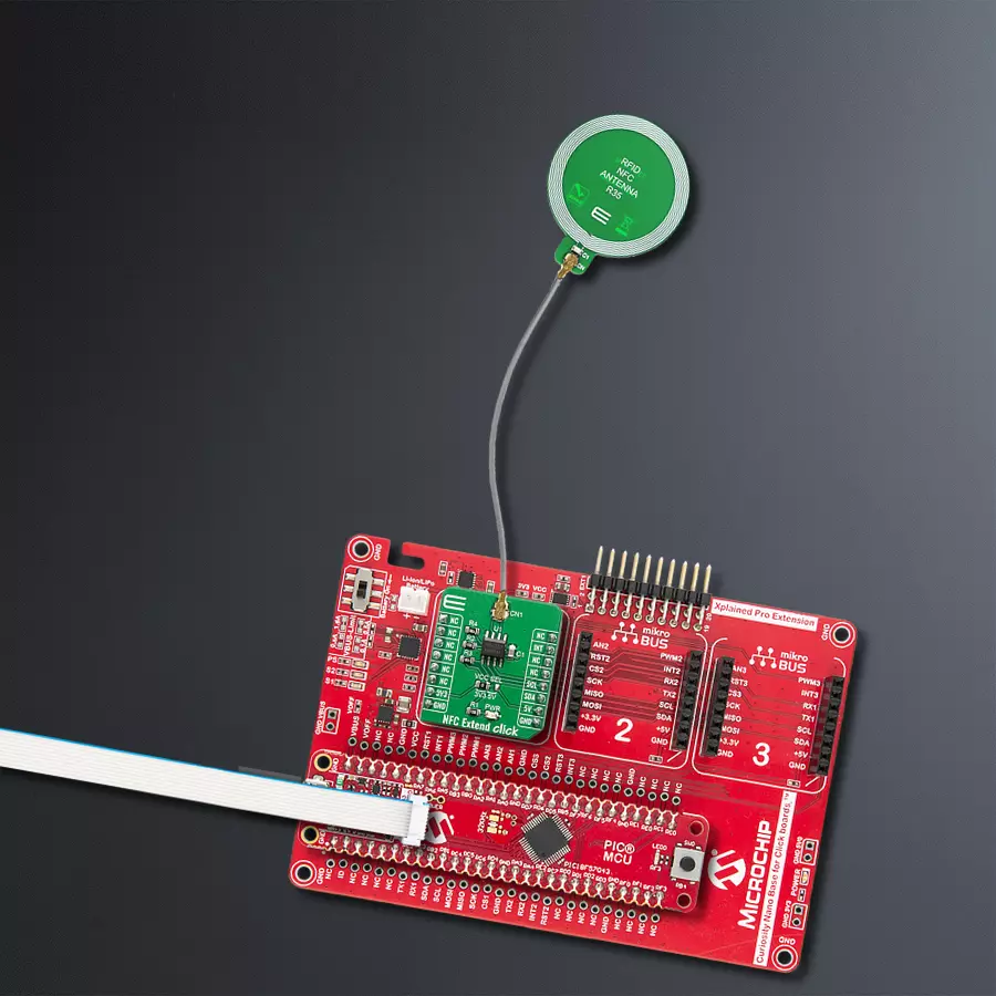
Curiosity Nano Base for Click boards is a versatile hardware extension platform created to streamline the integration between Curiosity Nano kits and extension boards, tailored explicitly for the mikroBUS™-standardized Click boards and Xplained Pro extension boards. This innovative base board (shield) offers seamless connectivity and expansion possibilities, simplifying experimentation and development. Key features include USB power compatibility from the Curiosity Nano kit, alongside an alternative external power input option for enhanced flexibility. The onboard Li-Ion/LiPo charger and management circuit ensure smooth operation for battery-powered applications, simplifying usage and management. Moreover, the base incorporates a fixed 3.3V PSU dedicated to target and mikroBUS™ power rails, alongside a fixed 5.0V boost converter catering to 5V power rails of mikroBUS™ sockets, providing stable power delivery for various connected devices.

Circular NFC R35 Antenna is a circular-shaped PCB antenna designed to be used as an extension of development boards and placed remotely on desired places such as plastic casing, existing products, or even under displays. The antenna is designed in a circular shape with a diameter of 35mm (35x42mm WxL) and seven coil turns. It's also important to mention that this antenna can be used for NFC and RFID applications that work on 13.56MHz frequency.

UMCC - Ultraminiature Coax Connector is an ultra-low profile 1.37mm diameter coax female-to-female interconnect solution that meets the ever-growing demand for miniaturization in next-generation wireless applications. Crafted as double-ended jumpers and inter-series assemblies, the UMCC cable also offers PCB jack receptacles for seamless board mount applications. With a length (L) of 200mm, a 2.5mm mated height (H), and a 50 Ohm characteristic impedance, the UMCC Connector Type III ensures optimal performance across a broad frequency range from DC to 6 GHz.

Used MCU Pins
mikroBUS™ mapper
Take a closer look
Click board™ Schematic
Step by step
Project assembly

Start by selecting your development board and Click board™. Begin with the Curiosity Nano with PIC18F57Q43 as your development board.


Track your results in real time
Application Output
1. Application Output - In Debug mode, the 'Application Output' window enables real-time data monitoring, offering direct insight into execution results. Ensure proper data display by configuring the environment correctly using the provided tutorial.

2. UART Terminal - Use the UART Terminal to monitor data transmission via a USB to UART converter, allowing direct communication between the Click board™ and your development system. Configure the baud rate and other serial settings according to your project's requirements to ensure proper functionality. For step-by-step setup instructions, refer to the provided tutorial.

3. Plot Output - The Plot feature offers a powerful way to visualize real-time sensor data, enabling trend analysis, debugging, and comparison of multiple data points. To set it up correctly, follow the provided tutorial, which includes a step-by-step example of using the Plot feature to display Click board™ readings. To use the Plot feature in your code, use the function: plot(*insert_graph_name*, variable_name);. This is a general format, and it is up to the user to replace 'insert_graph_name' with the actual graph name and 'variable_name' with the parameter to be displayed.

Software Support
Library Description
This library contains API for NFC Extend Click driver.
Key functions:
nfcextend_i2c_set- This function writes data to the chip.nfcextend_i2c_get- This function reads data from the chip.nfcextend_digital_read_int- This function reads the digital signal from the INT pin.
Open Source
Code example
The complete application code and a ready-to-use project are available through the NECTO Studio Package Manager for direct installation in the NECTO Studio. The application code can also be found on the MIKROE GitHub account.
/*!
 * \file
 * \brief NfcExtend Click example
 *
 * # Description
 * This example showcases how to configure and use the NFC Extend Click. The Click is an NFC tag
 * interface which uses the I2C serial interface and an RF link interface in order to communicate.
 * The example requires the ST25 NFC Tap application which can be downloaded to your phone.
 *
 * The demo application is composed of two sections :
 *
 * ## Application Init
 * This function initializes and configures the logger and Click modules.
 *
 * ## Application Task
 * This function waits for the interrupt signal, after which it expects data transfers. Once
 * some data has been detected it will open a communication channel with the device transmitting
 * it and show the received data in the UART console.
 *
 * \author MikroE Team
 *
 */
// ------------------------------------------------------------------- INCLUDES

#include "board.h"
#include "log.h"
#include "nfcextend.h"

// ------------------------------------------------------------------ VARIABLES

static nfcextend_t nfcextend;
static log_t logger;

uint8_t default_password[ NFCEXTEND_PASSWORD_LEN ] = { 0 };

// ------------------------------------------------------- ADDITIONAL FUNCTIONS

void wait_for_interrupt ( )
{
    uint8_t int_pin_flag;
    uint16_t timer_counter;

    int_pin_flag = nfcextend_digital_read_int( &nfcextend );
    timer_counter = 0;

    while ( ( int_pin_flag == 1 ) && ( timer_counter <= 300 ) )
    {
        Delay_ms ( 1 );
        timer_counter++;
        int_pin_flag = nfcextend_digital_read_int( &nfcextend );
    }

    if ( timer_counter <= 300 )
    {
        int_pin_flag = nfcextend_digital_read_int( &nfcextend );

        while ( int_pin_flag == 0 )
        {
            int_pin_flag = nfcextend_digital_read_int( &nfcextend );
        }
    }

    timer_counter = 0;
}

// ------------------------------------------------------ APPLICATION FUNCTIONS

void application_init ( )
{
    log_cfg_t log_cfg;
    nfcextend_cfg_t cfg;

    uint8_t init_status_flag;

    /**
     * Logger initialization.
     * Default baud rate: 115200
     * Default log level: LOG_LEVEL_DEBUG
     * @note If USB_UART_RX and USB_UART_TX
     * are defined as HAL_PIN_NC, you will
     * need to define them manually for log to work.
     * See @b LOG_MAP_USB_UART macro definition for detailed explanation.
     */
    LOG_MAP_USB_UART( log_cfg );
    log_init( &logger, &log_cfg );
    log_info( &logger, "---- Application Init ----" );

    //  Click initialization.

    nfcextend_cfg_setup( &cfg );
    NFCEXTEND_MAP_MIKROBUS( cfg, MIKROBUS_1 );
    nfcextend_init( &nfcextend, &cfg );

    nfcextend_password_present( &nfcextend, default_password );
    Delay_ms ( 100 );

    init_status_flag = nfcextend_default_cfg( &nfcextend );
    Delay_ms ( 100 );

    if ( 1 == init_status_flag )
    {
        log_printf( &logger, " * App init failed. *\r\n" );
    }
    else if ( 0 == init_status_flag )
    {
        log_printf( &logger, " * App init done. *\r\n" );
    }
    log_printf( &logger, "-----------------------\r\n" );
}

void application_task ( )
{
    nfcextend_block_t block;

    uint8_t temp_buf[ 258 ];
    uint16_t message_len;
    uint16_t cnt;

    block.memory_area = NFCEXTEND_MEMORY_DYNAMIC;
    block.reg_addr = NFCEXTEND_DYNAMIC_REG_MB_CTRL;
    block.data_buf = temp_buf;
    block.len = 1;

    wait_for_interrupt( );
    nfcextend_i2c_get( &nfcextend, &block );

    if ( ( temp_buf[ 0 ] & 0x04 ) == 0x04 )
    {
        block.reg_addr = NFCEXTEND_DYNAMIC_REG_MB_LEN;
        block.data_buf = &temp_buf[ 0 ];

        wait_for_interrupt( );
        nfcextend_i2c_get( &nfcextend, &block );

        message_len = temp_buf[ 0 ] + 1;

        block.memory_area = NFCEXTEND_MEMORY_MAILBOX;
        block.reg_addr = NFCEXTEND_MAILBOX_REG_BYTE_0;
        block.data_buf = &temp_buf[ 0 ];
        block.len = message_len;

        wait_for_interrupt( );
        nfcextend_i2c_get( &nfcextend, &block );

        log_printf( &logger, " ** Message length:  %u Bytes**\r\n", message_len);

        log_printf( &logger, " ------------------------------\r\n" );
        log_printf( &logger, " ** Message START **\r\n" );

        for ( cnt = 0; cnt < message_len; cnt++ )
        {
            log_printf( &logger, " %u : 0x%x\r\n", cnt, ( uint16_t ) temp_buf[ cnt ] );
        }

        log_printf( &logger, " ** Message END **\r\n" );
        log_printf( &logger, " ------------------------------\r\n" );
    }
}

int main ( void )
{
    /* Do not remove this line or clock might not be set correctly. */
    #ifdef PREINIT_SUPPORTED
    preinit();
    #endif

    application_init( );

    for ( ; ; )
    {
        application_task( );
    }

    return 0;
}

// ------------------------------------------------------------------------ END


