Unleash your creativity and showcase your content in style with MI9639BO-W and PIC18F57Q43
Illuminating possibilities

Published Feb 13, 2024
Click board™
OLED W Click
Dev. board
Curiosity Nano with PIC18F57Q43
Compiler
NECTO Studio
MCU
PIC18F57Q43
Capture attention and engage your audience with our mesmerizing 96x39px OLED solution, delivering stunning visuals in a compact form
A
A
Hardware Overview
How does it work?
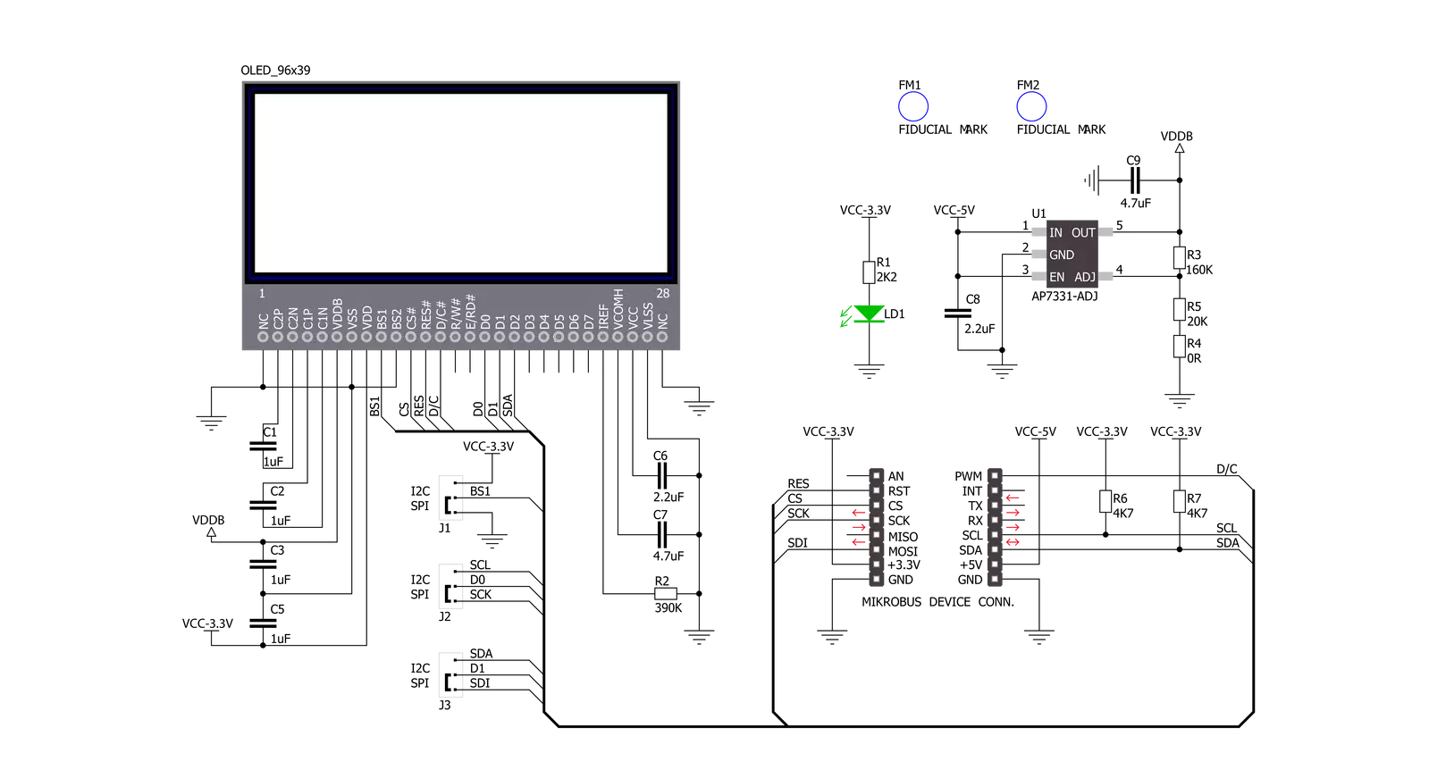
OLED W Click is based on the MI9639BO-W, a 19.3x7.8mm 96x39px white light monochrome passive matrix OLED display from Multi-Inno Technology. The MI9639BO-W display features an SSD1306, a 128x64 dot-matrix OLED/PLED segment/common driver with a controller. The controller has built-in functionalities like contrast control (256-step brightness control), normal or inverse image display, and vertical and horizontal scrolling functions, and more accessible through the configurable host interface. OLEDs are emissive and don't require a separate backlight as LCD technology does, reducing the OLED display's overall power consumption compared to LCDs. It also does not suffer from contrast loss due to the backlight's bleed-through in the "off" pixels. OLEDs, being emissive, have a consistent contrast ratio with no limitation in viewing angle. In addition, they don't suffer from temperature-
related response time delays and contrast changes. Like any OLED display, the MI9639BO-W is made from a thin film of an organic compound that emits bright light when exposed to a current with a wide viewing angle and low power consumption, representing an ideal solution for displaying text or icons. OLED W Click allows using both I2C and SPI interfaces. The selection can be made by positioning SMD jumpers labeled SEL COMM in an appropriate position. Note that all the jumpers' positions must be on the same side, or the Click board™ may become unresponsive. In addition, it uses two more pins. The first is related to the reset function, routed to the RST pin on the mikroBUS™ socket. When this pin is in a low logic state, the initialization of the SSD1306 is executed. The second pin is labeled as D/C and routed to the PWM pin on the mikroBUS™ socket representing the I2C slave address selection pin in a case of
selected I2C communication. In addition to the display's main power supply, taken from the +3.3V microBUS™ power rail, the MI9639BO-W has another power pin, more precisely, the power supply for its DC/DC converter circuit. This pin represents the power supply pin for the internal buffer of the DC/DC voltage converter, which is why this Click board™ uses a low dropout linear regulator AP7331 from Diodes Incorporated, providing a 3.6V power supply out of 5V mikroBUS™ rail. This Click board™ is designed to be operated only with a 3.3V logic voltage level, while 5V is used as a supply voltage of the LDO. The board must perform appropriate logic voltage level conversion before use with MCUs with different logic levels. However, the Click board™ comes equipped with a library containing easy-to-use functions and an example code that can be used, as a reference, for further development.

Features overview
Development board
PIC18F57Q43 Curiosity Nano evaluation kit is a cutting-edge hardware platform designed to evaluate microcontrollers within the PIC18-Q43 family. Central to its design is the inclusion of the powerful PIC18F57Q43 microcontroller (MCU), offering advanced functionalities and robust performance. Key features of this evaluation kit include a yellow user LED and a responsive
mechanical user switch, providing seamless interaction and testing. The provision for a 32.768kHz crystal footprint ensures precision timing capabilities. With an onboard debugger boasting a green power and status LED, programming and debugging become intuitive and efficient. Further enhancing its utility is the Virtual serial port (CDC) and a debug GPIO channel (DGI
GPIO), offering extensive connectivity options. Powered via USB, this kit boasts an adjustable target voltage feature facilitated by the MIC5353 LDO regulator, ensuring stable operation with an output voltage ranging from 1.8V to 5.1V, with a maximum output current of 500mA, subject to ambient temperature and voltage constraints.

Microcontroller Overview
MCU Card / MCU

Architecture
PIC
MCU Memory (KB)
128
Silicon Vendor
Microchip
Pin count
48
RAM (Bytes)
8196
You complete me!
Accessories
Curiosity Nano Base for Click boards is a versatile hardware extension platform created to streamline the integration between Curiosity Nano kits and extension boards, tailored explicitly for the mikroBUS™-standardized Click boards and Xplained Pro extension boards. This innovative base board (shield) offers seamless connectivity and expansion possibilities, simplifying experimentation and development. Key features include USB power compatibility from the Curiosity Nano kit, alongside an alternative external power input option for enhanced flexibility. The onboard Li-Ion/LiPo charger and management circuit ensure smooth operation for battery-powered applications, simplifying usage and management. Moreover, the base incorporates a fixed 3.3V PSU dedicated to target and mikroBUS™ power rails, alongside a fixed 5.0V boost converter catering to 5V power rails of mikroBUS™ sockets, providing stable power delivery for various connected devices.

Used MCU Pins
mikroBUS™ mapper
Take a closer look
Click board™ Schematic
Step by step
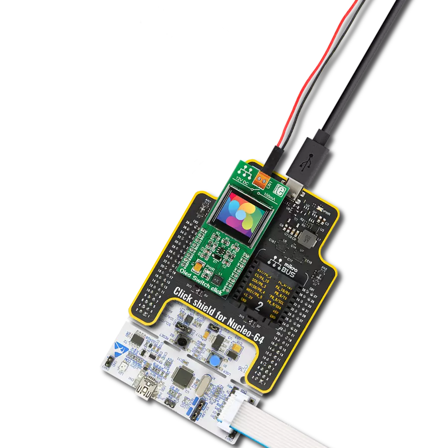
Project assembly

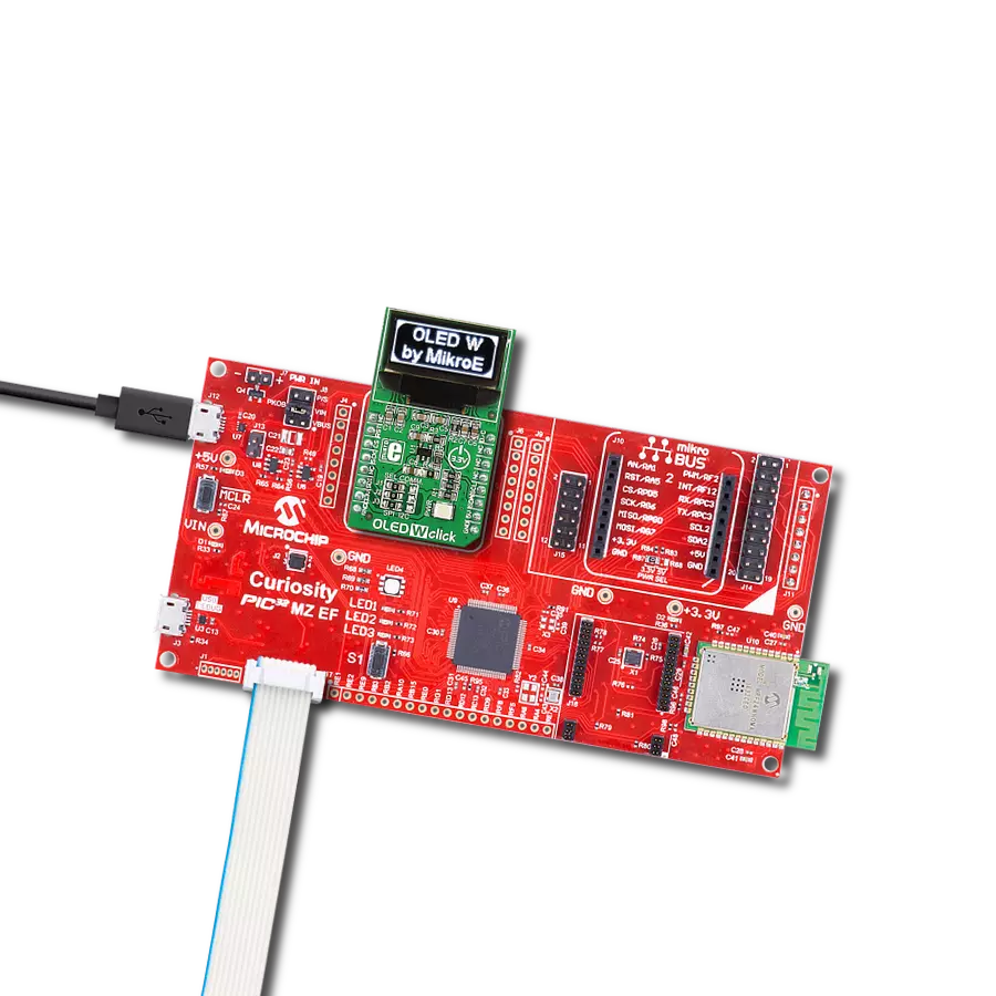
Start by selecting your development board and Click board™. Begin with the Curiosity Nano with PIC18F57Q43 as your development board.


Software Support
Library Description
This library contains API for OLED W Click driver.
Key functions:
oledw_send- This function sends commands or data to OLED W click.oledw_display_picture- This function allows user to display picture for page addressing mode.oledw_set_contrast- This function sets the display contrast level (0 to 255).
Open Source
Code example
The complete application code and a ready-to-use project are available through the NECTO Studio Package Manager for direct installation in the NECTO Studio. The application code can also be found on the MIKROE GitHub account.
/*!
 * @file main.c
 * @brief OLEDW Click example
 *
 # Description
 * This example demonstrates the use (control) of the OLED W display.
 *
 * The demo application is composed of two sections :
 *
 * ## Application Init
 * Configures the microcontroller for communication and initializes the Click
 * board to default state.
 *
 * ## Application Task
 * This section contains the main program that is executed showing a practical
 * example on how to use the implemented functions.
 *
 * @author Stefan Ilic
 *
 */

#include "board.h"
#include "log.h"
#include "oledw.h"
#include "resources.h"

static oledw_t oledw;
static log_t logger;

void application_init ( void ) {
    log_cfg_t log_cfg;  /**< Logger config object. */
    oledw_cfg_t oledw_cfg;  /**< Click config object. */

    /**
     * Logger initialization.
     * Default baud rate: 115200
     * Default log level: LOG_LEVEL_DEBUG
     * @note If USB_UART_RX and USB_UART_TX
     * are defined as HAL_PIN_NC, you will
     * need to define them manually for log to work.
     * See @b LOG_MAP_USB_UART macro definition for detailed explanation.
     */
    LOG_MAP_USB_UART( log_cfg );
    log_init( &logger, &log_cfg );
    Delay_ms ( 100 );
    log_info( &logger, " Application Init " );

    // Click initialization.
    oledw_cfg_setup( &oledw_cfg );
    OLEDW_MAP_MIKROBUS( oledw_cfg, MIKROBUS_1 );
    err_t init_flag  = oledw_init( &oledw, &oledw_cfg );
    if ( ( I2C_MASTER_ERROR == init_flag ) || ( SPI_MASTER_ERROR == init_flag ) ) {
        log_error( &logger, " Application Init Error. " );
        log_info( &logger, " Please, run program again... " );

        for ( ; ; );
    }

    oledw_default_cfg ( &oledw );
    log_info( &logger, " Application Task " );
}

void application_task ( void ) {
    uint8_t i;

    oledw_display_picture( &oledw, oledw_img );
    Delay_ms ( 500 );
    oledw_send( &oledw, OLEDW_INVERTDISPLAY, OLEDW_COMMAND );
    Delay_ms ( 500 );
    oledw_send( &oledw, OLEDW_NORMALDISPLAY, OLEDW_COMMAND );
    Delay_ms ( 500 );
    oledw_send( &oledw, OLEDW_INVERTDISPLAY, OLEDW_COMMAND );
    Delay_ms ( 500 );
    oledw_send( &oledw, OLEDW_NORMALDISPLAY, OLEDW_COMMAND );
    Delay_ms ( 300 );

    for (i = 0xAF; i > 0x00; i--) {
        oledw_set_contrast( &oledw, i );
        Delay_ms ( 5 );
    }

    for (i = 0x00; i < 0xAF; i++) {
        oledw_set_contrast( &oledw, i );
        Delay_ms ( 5 );
    }

    oledw_scroll_right( &oledw, 0x00, 0x05 );
    Delay_ms ( 1000 );
    oledw_stop_scroll( &oledw );
    oledw_display_picture( &oledw, oledw_img );

    oledw_scroll_left( &oledw, 0x00, 0x05 );
    Delay_ms ( 1000 );
    oledw_stop_scroll( &oledw );
    oledw_display_picture( &oledw, oledw_img );

    oledw_scroll_diag_right( &oledw, 0x00, 0x05 );
    Delay_ms ( 1000 );
    oledw_stop_scroll( &oledw );
    oledw_display_picture( &oledw, oledw_img );

    oledw_scroll_diag_left( &oledw, 0x00, 0x05 );
    Delay_ms ( 1000 );
    oledw_stop_scroll( &oledw );
}

int main ( void )
{
    /* Do not remove this line or clock might not be set correctly. */
    #ifdef PREINIT_SUPPORTED
    preinit();
    #endif

    application_init( );

    for ( ; ; )
    {
        application_task( );
    }

    return 0;
}

// ------------------------------------------------------------------------ END
Additional Support
Resources
Category:OLED