Process, move, and store information securely thanks to the SEC1210 and PIC18F57Q43
Elevate access control with smart card reading: Your key to a secure tomorrow

Published Feb 13, 2024
Click board™
Smart Card 2 Click
Dev. board
Curiosity Nano with PIC18F57Q43
Compiler
NECTO Studio
MCU
PIC18F57Q43
Explore the most advanced smart card reader on the market, offering unparalleled protection and ease of use
A
A
Hardware Overview
How does it work?
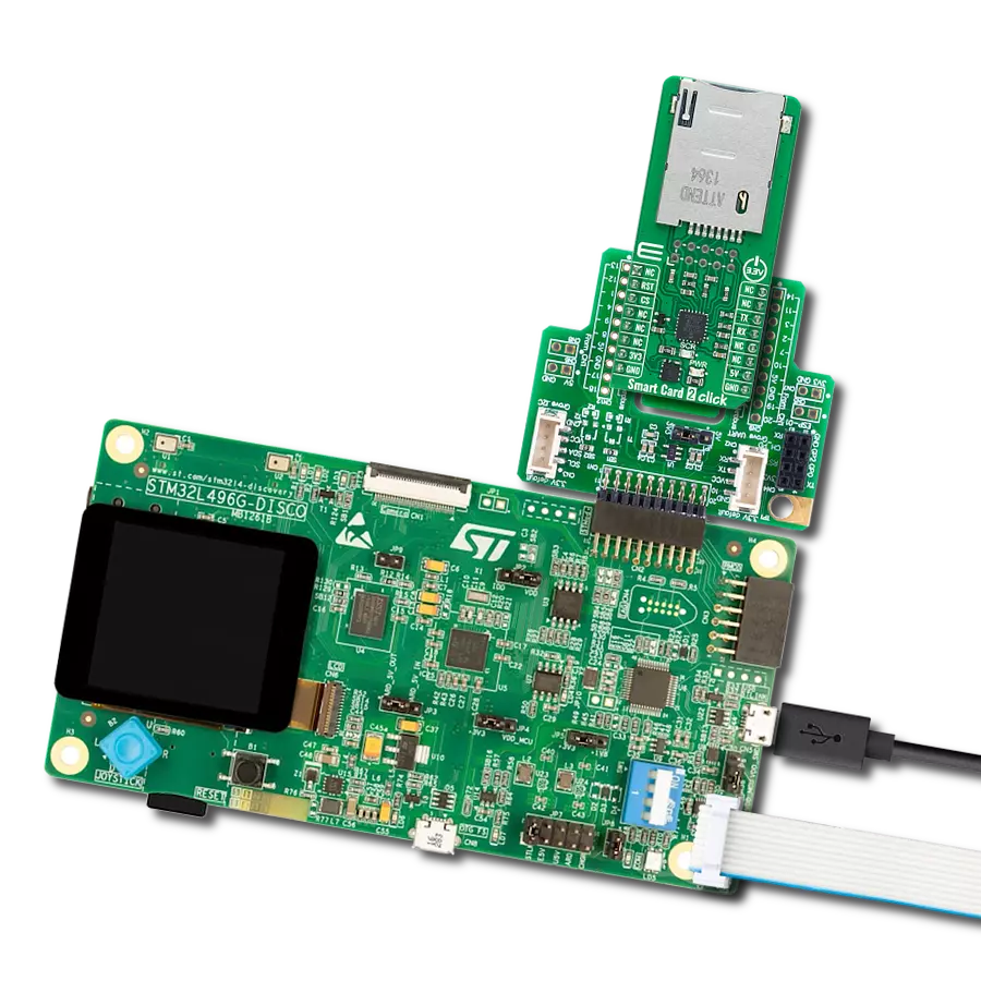
Smart Card 2 Click is based on the SEC1210, a high-performance single-chip Smart Card controller with a UART interface from Microchip. The SEC1210 is controlled by an enhanced integrated 8051 CPU, with all chip peripherals accessed and managed through the SFR or XDATA register space. Besides, it is fully compliant with the prevailing Smart Card standards (ISO7816, EMV, and PC/SC), keeps up with all requirements for communication bit rate, and includes support for proposed bit rates up to 826Kbps. The SEC1210 power unit is regulated and switched internally, supporting all 5V, 3V, and 1.8V Smart Cards (classes A, B, and C, respectively). The SEC1210 utilizes TrustSpan™ technology, enabling digital systems to communicate securely, process,
move, and store information. A populated onboard card holder supports data processing with 2FF smart cards. An additional connector for external connection also allows the processing of a standard 1FF card, making it ideal for electronic processes such as personal identification, access control (physical and logical access), authentication, and many more. This Click board™ communicates with MCU using the UART interface with commonly used UART RX/TX and operates at 115200 bps by default configuration to transmit and exchange data with the host MCU. The sequence activation/deactivation process itself is possible through software. Still, hardware deactivation is also supported when a card is
pulled out, whereby the required sequence is ensured regardless of software participation. In addition, Smart Card 2 Click also possesses a general Reset feature routed to the RST pin on the mikroBUS™ socket, which puts the module into a Reset state, while a yellow LED indicator labeled SRC represents a Smart Card status indicator. The blinking of this LED indicates that the Smart Card data processing is in progress. This Click board™ can operate with 3.3V and 5V MCUs, while SEC1210 uses only 5V from mikroBUS™ power rail as its primary power supply. However, the Click board™ comes equipped with a library containing functions and example code that can be used as a reference for further development.

Features overview
Development board
PIC18F57Q43 Curiosity Nano evaluation kit is a cutting-edge hardware platform designed to evaluate microcontrollers within the PIC18-Q43 family. Central to its design is the inclusion of the powerful PIC18F57Q43 microcontroller (MCU), offering advanced functionalities and robust performance. Key features of this evaluation kit include a yellow user LED and a responsive
mechanical user switch, providing seamless interaction and testing. The provision for a 32.768kHz crystal footprint ensures precision timing capabilities. With an onboard debugger boasting a green power and status LED, programming and debugging become intuitive and efficient. Further enhancing its utility is the Virtual serial port (CDC) and a debug GPIO channel (DGI
GPIO), offering extensive connectivity options. Powered via USB, this kit boasts an adjustable target voltage feature facilitated by the MIC5353 LDO regulator, ensuring stable operation with an output voltage ranging from 1.8V to 5.1V, with a maximum output current of 500mA, subject to ambient temperature and voltage constraints.

Microcontroller Overview
MCU Card / MCU

Architecture
PIC
MCU Memory (KB)
128
Silicon Vendor
Microchip
Pin count
48
RAM (Bytes)
8196
You complete me!
Accessories
Curiosity Nano Base for Click boards is a versatile hardware extension platform created to streamline the integration between Curiosity Nano kits and extension boards, tailored explicitly for the mikroBUS™-standardized Click boards and Xplained Pro extension boards. This innovative base board (shield) offers seamless connectivity and expansion possibilities, simplifying experimentation and development. Key features include USB power compatibility from the Curiosity Nano kit, alongside an alternative external power input option for enhanced flexibility. The onboard Li-Ion/LiPo charger and management circuit ensure smooth operation for battery-powered applications, simplifying usage and management. Moreover, the base incorporates a fixed 3.3V PSU dedicated to target and mikroBUS™ power rails, alongside a fixed 5.0V boost converter catering to 5V power rails of mikroBUS™ sockets, providing stable power delivery for various connected devices.

Used MCU Pins
mikroBUS™ mapper
Take a closer look
Click board™ Schematic

Step by step
Project assembly

Start by selecting your development board and Click board™. Begin with the Curiosity Nano with PIC18F57Q43 as your development board.


Software Support
Library Description
This library contains API for Smart Card 2 Click driver.
Key functions:
smartcard2_send_ccid- This function sends the CCID command message by using UART serial interfacesmartcard2_read_ccid- This function reads a CCID response or event message by using UART serial interfacesmartcard2_icc_power_on- This function activates the card by performing an ICC power ON command. The device will respond with a data block containing ICC ATR (Answer to Reset) message
Open Source
Code example
The complete application code and a ready-to-use project are available through the NECTO Studio Package Manager for direct installation in the NECTO Studio. The application code can also be found on the MIKROE GitHub account.
/*!
 * @file main.c
 * @brief Smart Card 2 Click Example.
 *
 * # Description
 * This example demonstrates the use of Smart Card 2 Click board by checking
 * the SIM card presence and activating the card on insert. The card should respond
 * with an ATR (Answer to Reset) message.
 *
 * The demo application is composed of two sections :
 *
 * ## Application Init
 * Initializes the driver and enables the device.
 *
 * ## Application Task
 * Reads and parses all CCID messages received from the device. Checks the SIM card presence
 * and activates it if it's inserted. The card should respond with an ATR (Answer to Reset) message.
 * All data is being logged on the USB UART where you can track their changes.
 *
 * @note
 * This example doesn't parse ATR messages.
 * There are some online ATR parsers which could be used for decoding those messages.
 * For example: https://smartcard-atr.apdu.fr/
 *
 * @author Stefan Filipovic
 *
 */

#include "board.h"
#include "log.h"
#include "smartcard2.h"

static smartcard2_t smartcard2;
static log_t logger;
static uint8_t icc_status = SMARTCARD2_ICC_ABSENT;

/**
 * @brief Smart Card 2 display ccid message function.
 * @details This function parses the CCID message and updates the icc_status in the end.
 * The results will be displayed on the USB UART.
 * @param[in] ccid : CCID message to be parsed.
 * See #smartcard2_ccid_t object definition for detailed explanation.
 * @return None.
 * @note None.
 */
static void smartcard2_display_ccid_message ( smartcard2_ccid_t ccid );

void application_init ( void )
{
    log_cfg_t log_cfg;  /**< Logger config object. */
    smartcard2_cfg_t smartcard2_cfg;  /**< Click config object. */

    /**
     * Logger initialization.
     * Default baud rate: 115200
     * Default log level: LOG_LEVEL_DEBUG
     * @note If USB_UART_RX and USB_UART_TX
     * are defined as HAL_PIN_NC, you will
     * need to define them manually for log to work.
     * See @b LOG_MAP_USB_UART macro definition for detailed explanation.
     */
    LOG_MAP_USB_UART( log_cfg );
    log_init( &logger, &log_cfg );
    log_info( &logger, " Application Init " );

    // Click initialization.
    smartcard2_cfg_setup( &smartcard2_cfg );
    SMARTCARD2_MAP_MIKROBUS( smartcard2_cfg, MIKROBUS_1 );
    if ( UART_ERROR == smartcard2_init( &smartcard2, &smartcard2_cfg ) )
    {
        log_error( &logger, " Communication init." );
        for ( ; ; );
    }

    log_info( &logger, " Application Task " );
}

void application_task ( void )
{
    smartcard2_ccid_t ccid = { 0 };
    if ( SMARTCARD2_OK == smartcard2_read_ccid ( &smartcard2, &ccid ) )
    {
        smartcard2_display_ccid_message ( ccid );
    }
    if ( SMARTCARD2_ICC_PRESENT == icc_status )
    {
        log_printf( &logger, " Activating card... \r\n" );
        smartcard2_icc_power_on ( &smartcard2, SMARTCARD2_POWER_SEL_3V );
        Delay_ms ( 100 );
    }
}

int main ( void )
{
    /* Do not remove this line or clock might not be set correctly. */
    #ifdef PREINIT_SUPPORTED
    preinit();
    #endif

    application_init( );

    for ( ; ; )
    {
        application_task( );
    }

    return 0;
}

static void smartcard2_display_ccid_message ( smartcard2_ccid_t ccid )
{
    log_printf( &logger, "---------------------------------\r\n" );
    switch ( ccid.type )
    {
        case SMARTCARD2_EVT_NOTIFY_SLOT_CHANGE:
        {
            log_printf( &logger, " Message type: Slot change\r\n" );
            if ( SMARTCARD2_CARD_ABSENT == ccid.payload[ 0 ] )
            {
                icc_status = SMARTCARD2_ICC_ABSENT;
            }
            else if ( SMARTCARD2_CARD_PRESENT == ccid.payload[ 0 ] )
            {
                icc_status = SMARTCARD2_ICC_PRESENT;
            }
            break;
        }
        case SMARTCARD2_CTRL_NACK:
        {
            log_printf( &logger, " Message type: NACK\r\n" );
            log_printf( &logger, " Command not acknowledged\r\n" );
            break;
        }
        case SMARTCARD2_RSP_SLOT_STATUS:
        {
            log_printf( &logger, " Message type: Slot status\r\n" );
            log_printf( &logger, " Slot number: 0x%.2X\r\n", ( uint16_t ) ccid.slot_num );
            log_printf( &logger, " Seq number: 0x%.2X\r\n", ( uint16_t ) ccid.seq_num );
            log_printf( &logger, " Status: 0x%.2X\r\n", ( uint16_t ) ccid.spec_bytes[ 0 ] );
            icc_status = ccid.spec_bytes[ 0 ] & SMARTCARD2_ICC_STATUS_MASK;
            log_printf( &logger, " Error: 0x%.2X\r\n", ( uint16_t ) ccid.spec_bytes[ 1 ] );
            log_printf( &logger, " Clock status: " );
            switch ( ccid.spec_bytes[ 2 ] )
            {
                case SMARTCARD2_CLK_STATUS_RUNNING:
                {
                    log_printf( &logger, "Running\r\n" );
                    break;
                }
                case SMARTCARD2_CLK_STATUS_STATE_L:
                {
                    log_printf( &logger, "Stoped in state L\r\n" );
                    break;
                }
                case SMARTCARD2_CLK_STATUS_STATE_H:
                {
                    log_printf( &logger, "Stoped in state H\r\n" );
                    break;
                }
                default:
                {
                    log_printf( &logger, "Unknown\r\n" );
                    break;
                }
            }
            break;
        }
        case SMARTCARD2_RSP_DATA_BLOCK:
        {
            log_printf( &logger, " Message type: Data Block\r\n" );
            log_printf( &logger, " Payload size: %lu\r\n", ccid.payload_size );
            log_printf( &logger, " Slot number: 0x%.2X\r\n", ( uint16_t ) ccid.slot_num );
            log_printf( &logger, " Seq number: 0x%.2X\r\n", ( uint16_t ) ccid.seq_num );
            log_printf( &logger, " Status: 0x%.2X\r\n", ( uint16_t ) ccid.spec_bytes[ 0 ] );
            icc_status = ccid.spec_bytes[ 0 ] & SMARTCARD2_ICC_STATUS_MASK;
            log_printf( &logger, " Error: 0x%.2X\r\n", ( uint16_t ) ccid.spec_bytes[ 1 ] );
            log_printf( &logger, " Chain parameter: 0x%.2X\r\n", ( uint16_t ) ccid.spec_bytes[ 2 ] );
            if ( ccid.payload_size )
            {
                log_printf( &logger, " Payload (ATR data as response to power on):\r\n" );
                for ( uint32_t cnt = 0; cnt < ccid.payload_size; cnt++ )
                {
                    log_printf( &logger, " %.2X", ( uint16_t ) ccid.payload[ cnt ] );
                }
                log_printf( &logger, "\r\n" );
            }
            break;
        }
        default:
        {
            log_printf( &logger, " Message type: 0x%.2X\r\n", ( uint16_t ) ccid.type );
            log_printf( &logger, " Payload size: %lu\r\n", ccid.payload_size );
            log_printf( &logger, " Slot number: 0x%.2X\r\n", ( uint16_t ) ccid.slot_num );
            log_printf( &logger, " Seq number: 0x%.2X\r\n", ( uint16_t ) ccid.seq_num );
            log_printf( &logger, " Spec bytes: 0x%.2X, 0x%.2X, 0x%.2X\r\n", ( uint16_t ) ccid.spec_bytes[ 0 ],
                                                                            ( uint16_t ) ccid.spec_bytes[ 1 ],
                                                                            ( uint16_t ) ccid.spec_bytes[ 2 ] );
            if ( ccid.payload_size )
            {
                log_printf( &logger, " Payload:\r\n" );
                for ( uint32_t cnt = 0; cnt < ccid.payload_size; cnt++ )
                {
                    log_printf( &logger, " 0x%.2X", ( uint16_t ) ccid.payload[ cnt ] );
                    if ( 7 == cnt % 8 )
                    {
                        log_printf( &logger, "\r\n" );
                    }
                }
                log_printf( &logger, "\r\n" );
            }
            break;
        }
    }
    if ( SMARTCARD2_ICC_ABSENT == icc_status )
    {
        log_printf( &logger, " ICC status: ABSENT\r\n" );
    }
    else if ( SMARTCARD2_ICC_PRESENT == icc_status )
    {
        log_printf( &logger, " ICC status: PRESENT\r\n" );
    }
    else if ( SMARTCARD2_ICC_ACTIVE == icc_status )
    {
        log_printf( &logger, " ICC status: ACTIVE\r\n" );
    }
    log_printf( &logger, "---------------------------------\r\n\n" );
}

// ------------------------------------------------------------------------ END
Additional Support
Resources
Category:Smart Card