Accurately monitor and control indoor climate conditions using BME280 and PIC18F57Q43
Tri-Meteo Nexus

Published Feb 13, 2024
Click board™
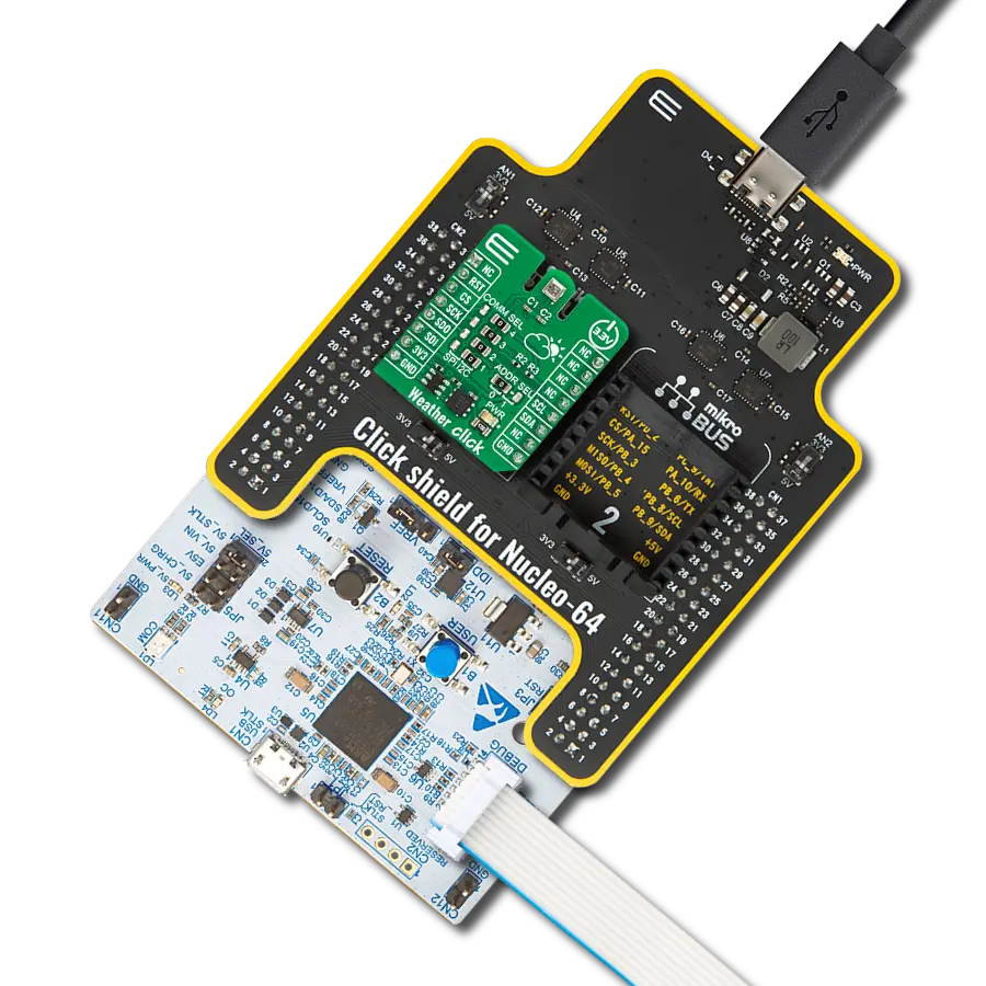
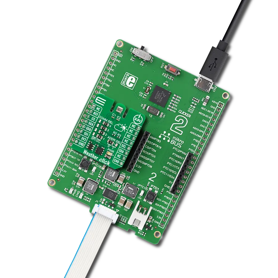
Weather Click
Dev. board
Curiosity Nano with PIC18F57Q43
Compiler
NECTO Studio
MCU
PIC18F57Q43
Enhance weather forecasting and environmental research with our integrated sensor solution, providing valuable data for meteorologists and scientists to analyze climate patterns and trends
A
A
Hardware Overview
How does it work?
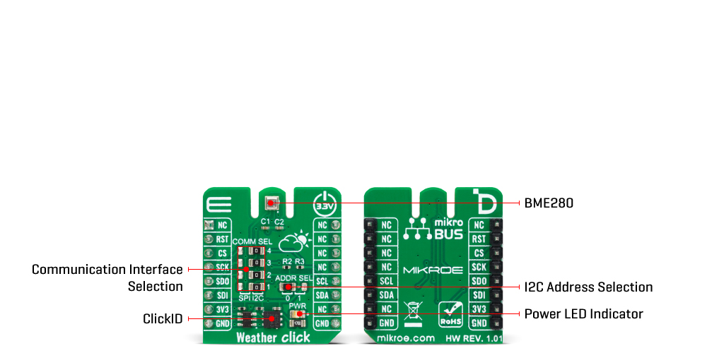
Weather Click is based on the BME280, a combined humidity and pressure sensor from Bosch Sensortec. The BME280 itself contains sensors from each of the environmental measurements. The humidity sensor has high overall accuracy and an extremely fast response time. The pressure sensor has extremely high accuracy and resolution as an absolute barometric sensor. The temperature sensor is basically used for temperature compensation, thus for accurate readings. Nevertheless, it has low noise and high resolution and can be used for ambient temperature readings. The Weather Click can work in one of three power modes. Sleep mode is the first mode the sensor enters after the Power-On reset, when no measurements are performed with
its power consumption at the minimum. In Forced mode, the sensor performs a single measurement and returns to Sleep mode. For the next measurement, the Forced mode must be selected again. The Normal mode means the sensor will take measurements in automated perpetual cycling between measurement and inactive periods. The sensors inside the BME280 have different output resolutions, with 16-bit ADC for humidity and up to 20-bit for pressure readings. An internal IIR filter helps suppress the disturbance of many shorter changes, such as a wind blowing into the sensor, slamming a door, and such. To achieve a high resolution and low noise of readings, the IIR filter must be enabled. Weather Click can use a standard 2-Wire I2C
interface supporting standard, fast, and high speeds or an SPI serial interface to communicate with the host MCU. The communication interface can be selected via SPI I2C 4-jumper sets, with the I2C interface selected by default. All four jumpers must be in place for the Weather Click to work properly. The I2C address can be selected via the ADDR jumper, with 0 set by default. This Click board™ can be operated only with a 3.3V logic voltage level. The board must perform appropriate logic voltage level conversion before using MCUs with different logic levels. Also, it comes equipped with a library containing functions and an example code that can be used as a reference for further development.
Features overview
Development board
PIC18F57Q43 Curiosity Nano evaluation kit is a cutting-edge hardware platform designed to evaluate microcontrollers within the PIC18-Q43 family. Central to its design is the inclusion of the powerful PIC18F57Q43 microcontroller (MCU), offering advanced functionalities and robust performance. Key features of this evaluation kit include a yellow user LED and a responsive
mechanical user switch, providing seamless interaction and testing. The provision for a 32.768kHz crystal footprint ensures precision timing capabilities. With an onboard debugger boasting a green power and status LED, programming and debugging become intuitive and efficient. Further enhancing its utility is the Virtual serial port (CDC) and a debug GPIO channel (DGI
GPIO), offering extensive connectivity options. Powered via USB, this kit boasts an adjustable target voltage feature facilitated by the MIC5353 LDO regulator, ensuring stable operation with an output voltage ranging from 1.8V to 5.1V, with a maximum output current of 500mA, subject to ambient temperature and voltage constraints.

Microcontroller Overview
MCU Card / MCU

Architecture
PIC
MCU Memory (KB)
128
Silicon Vendor
Microchip
Pin count
48
RAM (Bytes)
8196
You complete me!
Accessories
Curiosity Nano Base for Click boards is a versatile hardware extension platform created to streamline the integration between Curiosity Nano kits and extension boards, tailored explicitly for the mikroBUS™-standardized Click boards and Xplained Pro extension boards. This innovative base board (shield) offers seamless connectivity and expansion possibilities, simplifying experimentation and development. Key features include USB power compatibility from the Curiosity Nano kit, alongside an alternative external power input option for enhanced flexibility. The onboard Li-Ion/LiPo charger and management circuit ensure smooth operation for battery-powered applications, simplifying usage and management. Moreover, the base incorporates a fixed 3.3V PSU dedicated to target and mikroBUS™ power rails, alongside a fixed 5.0V boost converter catering to 5V power rails of mikroBUS™ sockets, providing stable power delivery for various connected devices.

Used MCU Pins
mikroBUS™ mapper
Take a closer look
Click board™ Schematic

Step by step
Project assembly

Start by selecting your development board and Click board™. Begin with the Curiosity Nano with PIC18F57Q43 as your development board.


Software Support
Library Description
This library contains API for Weather Click driver.
Key functions:
weather_get_ambient_data- Use this function to read the temperature, pressure and humidity dataweather_get_device_id- You can use this function as a check on click communication with your MCUweather_measurement_cfg- Use this function to set up new settings
Open Source
Code example
The complete application code and a ready-to-use project are available through the NECTO Studio Package Manager for direct installation in the NECTO Studio. The application code can also be found on the MIKROE GitHub account.
/*!
 * @file
 * @brief Weather Click example
 *
 * # Description
 * This demo-app shows the temperature, pressure and humidity measurement using Weather Click.
 *
 * The demo application is composed of two sections :
 *
 * ## Application Init
 * Configuring Clicks and log objects.
 * Setting the Click in the default configuration to start the measurement.
 *
 * ## Application Task
 * Reads Temperature data, Relative Humidity data and Pressure data,
 * and displays them on USB UART every 1500ms.
 *
 * @author MikroE Team
 *
 */

#include "board.h"
#include "log.h"
#include "weather.h"

static weather_t weather;
static log_t logger;

void application_init ( void )
{
    log_cfg_t log_cfg;
    weather_cfg_t weather_cfg;

    /**
     * Logger initialization.
     * Default baud rate: 115200
     * Default log level: LOG_LEVEL_DEBUG
     * @note If USB_UART_RX and USB_UART_TX
     * are defined as HAL_PIN_NC, you will
     * need to define them manually for log to work.
     * See @b LOG_MAP_USB_UART macro definition for detailed explanation.
     */
    LOG_MAP_USB_UART( log_cfg );
    log_init( &logger, &log_cfg );
    log_info( &logger, " Application Init " );

    // Click initialization.
    weather_cfg_setup( &weather_cfg );
    WEATHER_MAP_MIKROBUS( weather_cfg, MIKROBUS_1 );
    if ( WEATHER_OK != weather_init( &weather, &weather_cfg ) )
    {
        log_error( &logger, " Communication init." );
        for ( ; ; );
    }

    if ( WEATHER_OK != weather_default_cfg ( &weather ) )
    {
        log_error( &logger, " Default configuration." );
        for ( ; ; );
    }

    log_info( &logger, " Application Task " );
}

void application_task ( void )
{
    weather_data_t weather_data;

    if ( WEATHER_OK == weather_get_ambient_data( &weather, &weather_data ) )
    {
        log_printf( &logger, " \r\n ---- Weather data ----- \r\n" );
        log_printf( &logger, "[PRESSURE]: %.2f mBar.\n\r", weather_data.pressure );
        log_printf( &logger, "[TEMPERATURE]: %.2f C.\n\r", weather_data.temperature );
        log_printf( &logger, "[HUMIDITY]: %.2f %%.\n\r", weather_data.humidity );

        Delay_ms ( 1000 );
        Delay_ms ( 500 );
    }
}

int main ( void )
{
    /* Do not remove this line or clock might not be set correctly. */
    #ifdef PREINIT_SUPPORTED
    preinit();
    #endif

    application_init( );

    for ( ; ; )
    {
        application_task( );
    }

    return 0;
}


// ------------------------------------------------------------------------ END
Additional Support
Resources
Category:Environmental