Achieve more accurate positioning, navigation, and interaction with 13DOF and ATmega328
The future of motion sensing has arrived
Published Feb 14, 2024
Click board™
13DOF Click
Dev. board
Arduino UNO Rev3
Compiler
NECTO Studio
MCU
ATmega328
Discover how sensor fusion with 13 degrees of freedom opens up endless opportunities for creating smarter, more responsive devices and systems.
A
A
Hardware Overview
How does it work?
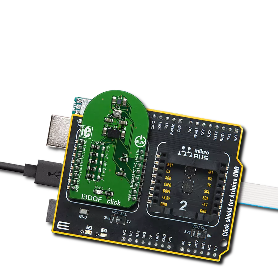
13DOF Click is based on the BME680 and the BMM150 sensor ICs. Also, the click contains BMI088 - a small, versatile 6DoF sensor module from Bosch Sensortec. Altogether, this Click board™ integrates a triaxial accelerometer, triaxial gyroscope, triaxial geomagnetic, gas, humidity, pressure and temperature sensors on the single board. This allows very high integration and very small dimensions, at an affordable cost. The output of each MEMS is processed, digitized and available through the I2C communication interface. The data can be oversampled by the sensor ICs by themselves, in order to achieve as reliable data readings as possible. As already mentioned, the features of this click are numerous. The BMM150 geomagnetic sensor from Bosch is a standalone sensor for consumer market applications. It allows measurements of the magnetic field in three perpendicular axes. The sensor is carefully tuned and a perfect match for the demanding requirements of all 3-axis mobile apps such as electronic compass, navigation or augmented reality.An application specific circuit (ASIC) converts the output of the geomagnetic sensor to digital results which can be read out over the industry standard digital I2C interface. Package and interfaces of the BMM150 have been designed to match a multitude of hardware
requirements. As the sensor features an ultra-small footprint and a flat package, it is ingeniously suited for mobile applications, such as cell phones, handhelds, computer peripherals, man-machine interfaces, virtual reality features, game controllers, and other. The BMI088 is an inertial measurement unit (IMU) for the detection of movements and rotations in 6 degrees of freedom (6DoF). It reflects the full functionality of a triaxial, low-g acceleration sensor and at the same time it is capable to measure angular rates. Both – acceleration and angular rate – in three perpendicular room dimensions, the x-, y- and z-axis. The BMI088 is designed to meet all requirements for consumer applications such as gaming and pointing devices, HMI and image stabilization (DSC and camera-phone). It also senses tilt, motion, inactivity and shock vibration in cell phones, handhelds, computer peripherals, HMI interfaces, virtual reality features and game controllers. An ASIC converts the output of the MEMS, developed, produced and tested in BOSCH facilities. To provide maximum performance and reliability each device is tested and ready-to-use calibrated. On the other side, the BME680 - a small, high performance, low power, 4-in-1 sensor is in charge for the gas, humidity, pressure and temperature measurements. It also features very low power
consumption, for example, 3.7µA is typical at 1 Hz humidity, pressure and temperature measurement mode. It also features a very high accuracy humidity sensor (tolerance ±3% r.H. and hysteresis ±1.5% r.H.), pressure sensor with only 0.12 Pa RMS Noise (equivalent to to 1.7 cm of altitude) and a very low temperature offset drift, and a gas sensor with direct indoor air quality (IAQ) index output system. In principle, the IAQ index output is in an index that can have values between 0 and 500 with a resolution of 1 to indicate or quantify the quality of the air available in the surrounding. It greatly simplifies the categorization of the air quality measurements. 13DOF click supports I2C communication interface, allowing it to be used with a wide range of different MCUs. The I2C slave address for the communication can be selected by moving SMD jumpers grouped under the COMM SEL to an appropriate position. This Click board™ can be operated only with a 3.3V logic voltage level. The board must perform appropriate logic voltage level conversion before using MCUs with different logic levels. Also, it comes equipped with a library containing functions and an example code that can be used as a reference for further development.


Features overview
Development board
Arduino UNO is a versatile microcontroller board built around the ATmega328P chip. It offers extensive connectivity options for various projects, featuring 14 digital input/output pins, six of which are PWM-capable, along with six analog inputs. Its core components include a 16MHz ceramic resonator, a USB connection, a power jack, an
ICSP header, and a reset button, providing everything necessary to power and program the board. The Uno is ready to go, whether connected to a computer via USB or powered by an AC-to-DC adapter or battery. As the first USB Arduino board, it serves as the benchmark for the Arduino platform, with "Uno" symbolizing its status as the
first in a series. This name choice, meaning "one" in Italian, commemorates the launch of Arduino Software (IDE) 1.0. Initially introduced alongside version 1.0 of the Arduino Software (IDE), the Uno has since become the foundational model for subsequent Arduino releases, embodying the platform's evolution.

Microcontroller Overview
MCU Card / MCU

Architecture
AVR
MCU Memory (KB)
32
Silicon Vendor
Microchip
Pin count
32
RAM (Bytes)
2048
You complete me!
Accessories
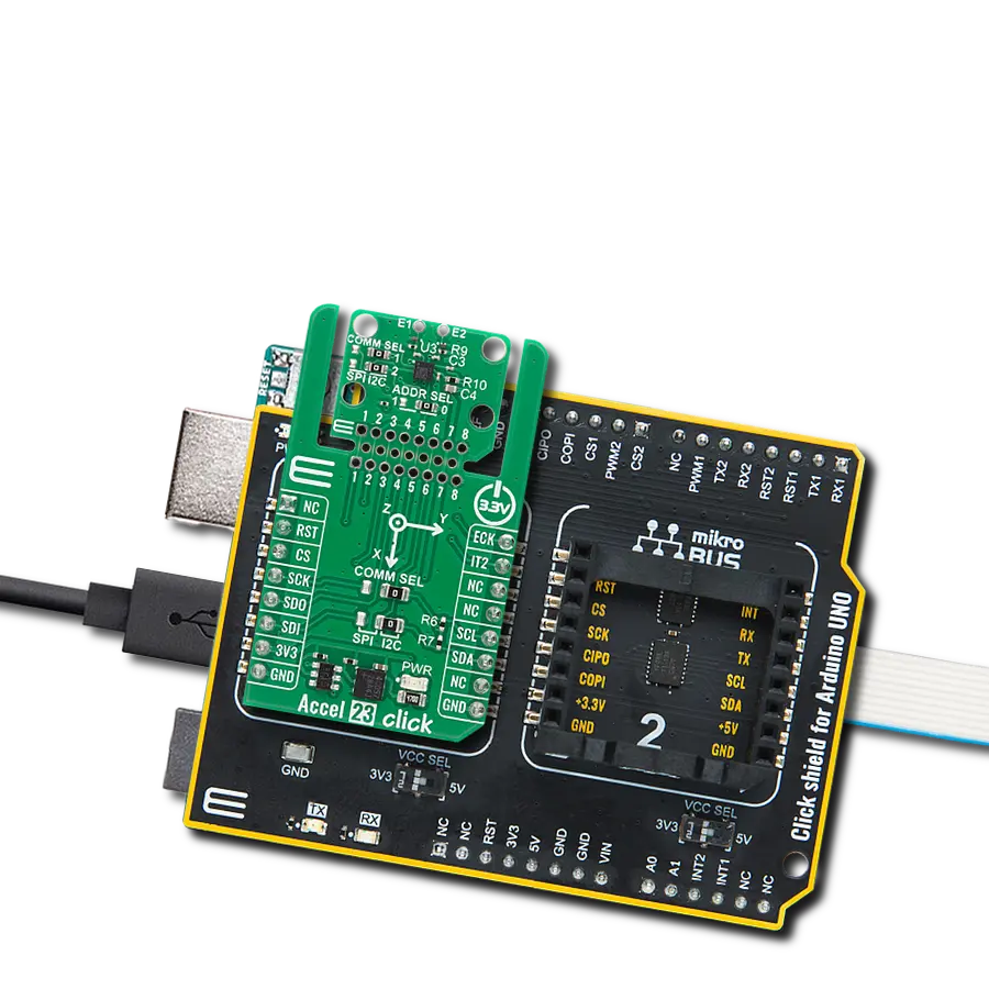
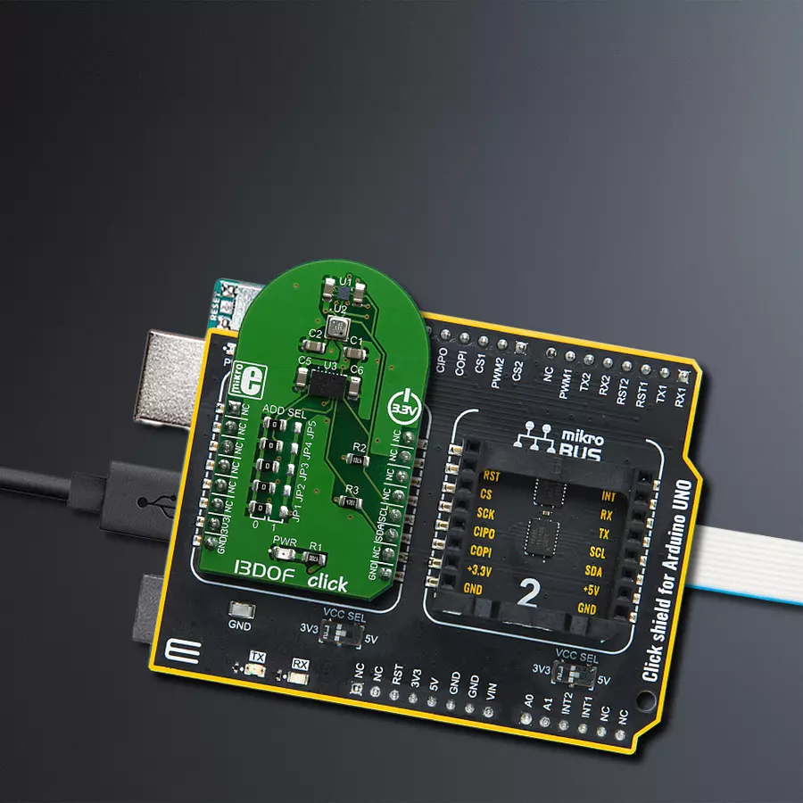
Click Shield for Arduino UNO has two proprietary mikroBUS™ sockets, allowing all the Click board™ devices to be interfaced with the Arduino UNO board without effort. The Arduino Uno, a microcontroller board based on the ATmega328P, provides an affordable and flexible way for users to try out new concepts and build prototypes with the ATmega328P microcontroller from various combinations of performance, power consumption, and features. The Arduino Uno has 14 digital input/output pins (of which six can be used as PWM outputs), six analog inputs, a 16 MHz ceramic resonator (CSTCE16M0V53-R0), a USB connection, a power jack, an ICSP header, and reset button. Most of the ATmega328P microcontroller pins are brought to the IO pins on the left and right edge of the board, which are then connected to two existing mikroBUS™ sockets. This Click Shield also has several switches that perform functions such as selecting the logic levels of analog signals on mikroBUS™ sockets and selecting logic voltage levels of the mikroBUS™ sockets themselves. Besides, the user is offered the possibility of using any Click board™ with the help of existing bidirectional level-shifting voltage translators, regardless of whether the Click board™ operates at a 3.3V or 5V logic voltage level. Once you connect the Arduino UNO board with our Click Shield for Arduino UNO, you can access hundreds of Click boards™, working with 3.3V or 5V logic voltage levels.

Used MCU Pins
mikroBUS™ mapper
Take a closer look
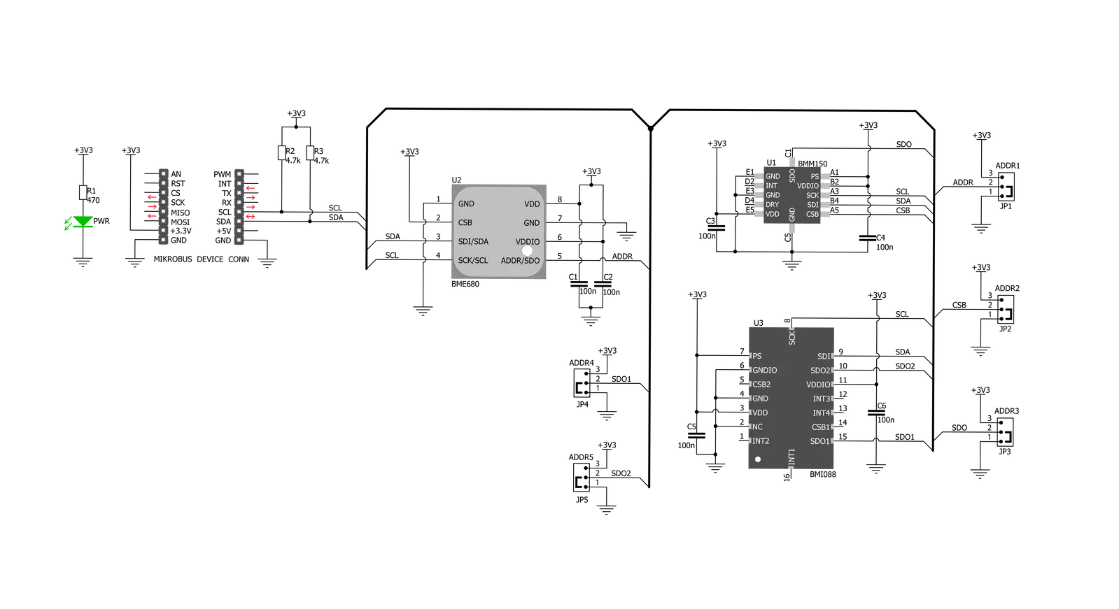
Click board™ Schematic
Step by step
Project assembly

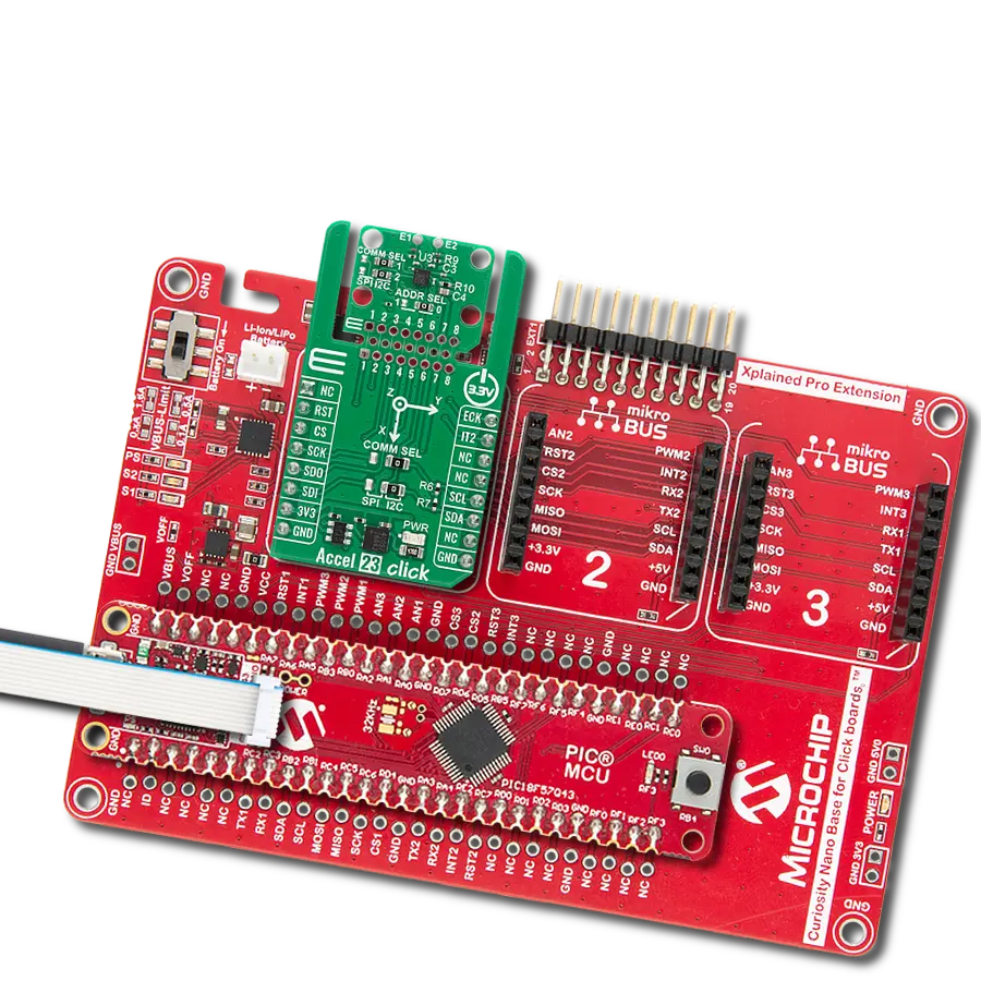
Start by selecting your development board and Click board™. Begin with the Arduino UNO Rev3 as your development board.


Software Support
Library Description
This library contains API for 13DOF Click driver.
Key functions:
c13dof_bmi088_read_accel- Function reads 16-bit X-axis, Y-axis data and Z-axis datac13dof_bmi088_accel_read_bytes- Function read a sequential data starting from the targeted 8-bit register addressc13dof_bmi088_read_gyro- Function reads 16-bit X-axis, Y-axis data and Z-axis data of BMM150 sensor on 13DOF Click
Open Source
Code example
The complete application code and a ready-to-use project are available through the NECTO Studio Package Manager for direct installation in the NECTO Studio. The application code can also be found on the MIKROE GitHub account.
/*!
 * \file
 * \brief c13DOF Click example
 *
 * # Description
 * This example displays values registered by sensors on Click board.
 *
 * The demo application is composed of two sections :
 *
 * ## Application Init
 * Initialization driver enables -
 * BME680 Low power gas, pressure, temperature & humidity sensor,
 * BMI088 6-axis Motion Tracking Sensor and
 * BMM150 Geomagnetic Sensor, also write log.
 *
 * ## Application Task
 * This is a example which demonstrates the use of 13DOF Click board.
 * Measures and display temperature in degrees Celsius [ C ], humidity data [ % ],
 * pressure [ mbar ] and gas resistance data from the BME680 sensor.
 * Measures and display Accel and Gyro data coordinates values
 * for X-axis, Y-axis and Z-axis from the BMI088 sensor.
 * Measures and display Geomagnetic data coordinates values for
 * X-axis, Y-axis and Z-axis from the BMM150 sensor.
 * Results are being sent to the Usart Terminal where you can track their changes.
 * All data logs write on usb uart changes for each second.
 *
 *
 * \author MikroE Team
 *
 */
// ------------------------------------------------------------------- INCLUDES

#include "board.h"
#include "log.h"
#include "c13dof.h"

// ------------------------------------------------------------------ VARIABLES

static c13dof_t c13dof;
static log_t logger;
float temperature;
float pressure;
float humidity;
int32_t gas_res;
int16_t accel_x;
int16_t accel_y;
int16_t accel_z;
int16_t gyro_x;
int16_t gyro_y;
int16_t gyro_z;
int16_t mag_x;
int16_t mag_y;
int16_t mag_z;
uint16_t r_hall;
uint8_t ready_check;

// ------------------------------------------------------ APPLICATION FUNCTIONS

void application_init ( void )
{
    log_cfg_t log_cfg;
    c13dof_cfg_t cfg;

    /**
     * Logger initialization.
     * Default baud rate: 115200
     * Default log level: LOG_LEVEL_DEBUG
     * @note If USB_UART_RX and USB_UART_TX
     * are defined as HAL_PIN_NC, you will
     * need to define them manually for log to work.
     * See @b LOG_MAP_USB_UART macro definition for detailed explanation.
     */
    LOG_MAP_USB_UART( log_cfg );
    log_init( &logger, &log_cfg );
    log_info( &logger, "---- Application Init ----" );

    //  Click initialization.

    c13dof_cfg_setup( &cfg );
    C13DOF_MAP_MIKROBUS( cfg, MIKROBUS_1 );
    c13dof_init( &c13dof, &cfg );
    c13dof_default_cfg( &c13dof );
}

void application_task ( void )
{
    temperature = c13dof_bme680_get_temperature( &c13dof );

    log_printf( &logger, "----------------------------------------------------------\n");
    log_printf( &logger, "Temperature : %.2f C \r\n", temperature );

    humidity = c13dof_bme680_get_humidity( &c13dof );
    log_printf( &logger, "Humidity : %.2f %% \r\n", humidity );

    pressure = c13dof_bme680_get_pressure( &c13dof );
    log_printf( &logger, "Pressure : %.2f mbar \r\n", pressure );

    gas_res = c13dof_bme680_get_gas_resistance( &c13dof );
    log_printf( &logger, "Gas Resistance : %ld \r\n", gas_res );

    ready_check = c13dof_bmm150_check_ready( &c13dof );

    while ( ready_check != C13DOF_BMM150_DATA_READY )
    {
        ready_check = c13dof_bmm150_check_ready( &c13dof );
    }

    c13dof_bmi088_read_accel( &c13dof, &accel_x, &accel_y, &accel_z );
    c13dof_bmi088_read_gyro( &c13dof, &gyro_x, &gyro_y, &gyro_z );
    c13dof_bmm150_read_geo_mag_data( &c13dof, &mag_x, &mag_y, &mag_z, &r_hall );

    log_printf( &logger, "Accel X : %d ", accel_x );
    log_printf( &logger, " Y : %d ", accel_y );
    log_printf( &logger, " Z : %d \r\n", accel_z );

    log_printf( &logger, "Gyro X : %d ", gyro_x );
    log_printf( &logger, " Y : %d ", gyro_y );
    log_printf( &logger, " Z : %d \r\n", gyro_z );

    log_printf( &logger, "Mag X : %d ", mag_x );
    log_printf( &logger, " Y : %d ", mag_y );
    log_printf( &logger, " Z : %d \r\n", mag_z );

    Delay_ms ( 1000 );
}

int main ( void )
{
    /* Do not remove this line or clock might not be set correctly. */
    #ifdef PREINIT_SUPPORTED
    preinit();
    #endif

    application_init( );

    for ( ; ; )
    {
        application_task( );
    }

    return 0;
}


// ------------------------------------------------------------------------ END
Additional Support
Resources
Category:Motion