Empower your project with precise motion-sensing capabilities using ISM330DLC and ATmega328
3 axes + 3 dimensions = limitless possibilities

Published Feb 14, 2024
Click board™
6DOF IMU 8 Click
Dev. board
Arduino UNO Rev3
Compiler
NECTO Studio
MCU
ATmega328
Enhance logistics and automation processes by monitoring and optimizing the movement of goods, robots, and machinery, improving overall supply chain efficiency
A
A
Hardware Overview
How does it work?
6DOF IMU 8 Click is based on the ISM330DLC, a 3D accelerometer and 3D gyroscope with digital output for industrial applications from STMicroelectronics. It is an advanced inertial module from iNEMO series, featuring an integrated microelectromechanical gyroscope and an accelerometer sensor (MEMS) within the same package. This device is designed with Industry 4.0 in mind, and produced using well-proven CMOS and MEMS fabrication processes, providing a high integration scale on a wafer level. This allows for a very good matching between the IC and the MEMS, offering very good robustness, mechanical shock immunity, and improved stability. Three-axis gyroscope MEMS can be programmed to measure the rotation about each axis, in five different ranges of angular speed (degrees per angle, dps): ±125, ±250, ±500, ±1000, and ±2000. Three-axis accelerometer MEMS can be programmed to measure the acceleration along each axis, in four different acceleration ranges: ±2g, ±4g, ±8g, and ±16g. The developer can select an optimal range for both properties, depending on the application requirements. The ISM330DLC incorporates a
powerful programmable interrupt engine with two dedicated interrupt pins. The interrupt engine can detect many different events, including free-fall, wakeup, 6D orientation, tap, and double-tap events, activity and inactivity recognition, as well as a tilt detection with two configurable event detection options: an average window and an average threshold. The function of these two interrupt pins is not limited to these events. They can also be used for FIFO buffer-related events, such as a buffer is full, the buffer is empty, watermark level is reached, and the buffer is overrun. Data Ready event can also be signaled for each of the two sensors (gyro and accel). The INT 1 pin is routed to the mikroBUS™ INT pin, while the INT 2 pin is routed to the mikroBUS™ AN pin. These pins are labeled as IT1 and IT2 on the Click board™, respectively. A FIFO buffer helps to reduce the communication bus traffic, processing load, and the power consumption, offering temporary storage for the output data. The ISM330DLC features a smart FIFO buffer with the capacity of 4096 bytes, which can be set to work in five different modes. The FIFO buffer is highly
configurable. It is possible to select the data to be stored from several sources (gyroscope, accelerometer, timestamp, temperature…). As already discussed, the FIFO buffer itself can trigger interrupt for several events, alerting the host MCU about its status. 6DOF IMU 8 click supports both SPI and I2C communication interfaces, allowing it to be used with a wide range of different MCUs. The communication interface can be selected by moving SMD jumpers grouped under the COM SEL to an appropriate position (SPI or I2C). The slave I2C address can also be configured by an SMD jumper when the Click board™ is operated in the I2C mode an SMD jumper labeled as ADD LSB is used to set the least significant bit (LSB) of the I2C address. When set to 1, the 7-bit I2C slave address becomes 0b1101011x. If set to 0, the address becomes 0b1101010x. The last digit (x) is the R/W bit. This Click Board™ uses both I2C and SPI communication interfaces. It is designed to be operated only with up to 3.3V logic levels. Proper conversion of logic voltage levels should be applied, before the Click board™ is used with MCUs operated at 5V.


Features overview
Development board
Arduino UNO is a versatile microcontroller board built around the ATmega328P chip. It offers extensive connectivity options for various projects, featuring 14 digital input/output pins, six of which are PWM-capable, along with six analog inputs. Its core components include a 16MHz ceramic resonator, a USB connection, a power jack, an
ICSP header, and a reset button, providing everything necessary to power and program the board. The Uno is ready to go, whether connected to a computer via USB or powered by an AC-to-DC adapter or battery. As the first USB Arduino board, it serves as the benchmark for the Arduino platform, with "Uno" symbolizing its status as the
first in a series. This name choice, meaning "one" in Italian, commemorates the launch of Arduino Software (IDE) 1.0. Initially introduced alongside version 1.0 of the Arduino Software (IDE), the Uno has since become the foundational model for subsequent Arduino releases, embodying the platform's evolution.

Microcontroller Overview
MCU Card / MCU

Architecture
AVR
MCU Memory (KB)
32
Silicon Vendor
Microchip
Pin count
32
RAM (Bytes)
2048
You complete me!
Accessories
Click Shield for Arduino UNO has two proprietary mikroBUS™ sockets, allowing all the Click board™ devices to be interfaced with the Arduino UNO board without effort. The Arduino Uno, a microcontroller board based on the ATmega328P, provides an affordable and flexible way for users to try out new concepts and build prototypes with the ATmega328P microcontroller from various combinations of performance, power consumption, and features. The Arduino Uno has 14 digital input/output pins (of which six can be used as PWM outputs), six analog inputs, a 16 MHz ceramic resonator (CSTCE16M0V53-R0), a USB connection, a power jack, an ICSP header, and reset button. Most of the ATmega328P microcontroller pins are brought to the IO pins on the left and right edge of the board, which are then connected to two existing mikroBUS™ sockets. This Click Shield also has several switches that perform functions such as selecting the logic levels of analog signals on mikroBUS™ sockets and selecting logic voltage levels of the mikroBUS™ sockets themselves. Besides, the user is offered the possibility of using any Click board™ with the help of existing bidirectional level-shifting voltage translators, regardless of whether the Click board™ operates at a 3.3V or 5V logic voltage level. Once you connect the Arduino UNO board with our Click Shield for Arduino UNO, you can access hundreds of Click boards™, working with 3.3V or 5V logic voltage levels.

Used MCU Pins
mikroBUS™ mapper
Take a closer look
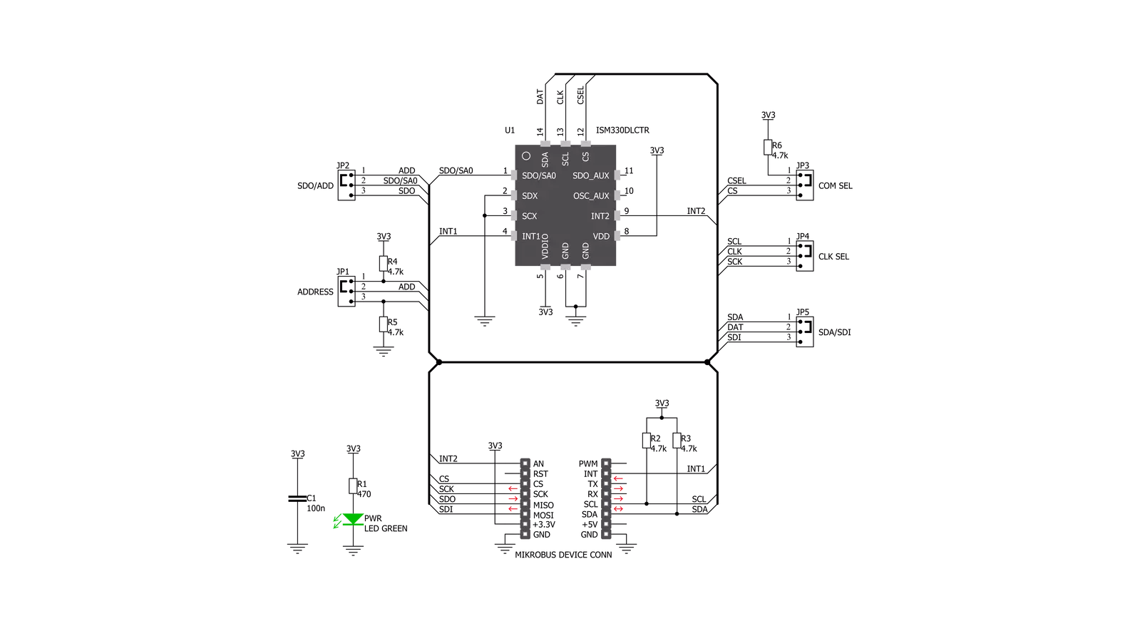
Click board™ Schematic
Step by step
Project assembly

Start by selecting your development board and Click board™. Begin with the Arduino UNO Rev3 as your development board.


Track your results in real time
Application Output
1. Application Output - In Debug mode, the 'Application Output' window enables real-time data monitoring, offering direct insight into execution results. Ensure proper data display by configuring the environment correctly using the provided tutorial.

2. UART Terminal - Use the UART Terminal to monitor data transmission via a USB to UART converter, allowing direct communication between the Click board™ and your development system. Configure the baud rate and other serial settings according to your project's requirements to ensure proper functionality. For step-by-step setup instructions, refer to the provided tutorial.

3. Plot Output - The Plot feature offers a powerful way to visualize real-time sensor data, enabling trend analysis, debugging, and comparison of multiple data points. To set it up correctly, follow the provided tutorial, which includes a step-by-step example of using the Plot feature to display Click board™ readings. To use the Plot feature in your code, use the function: plot(*insert_graph_name*, variable_name);. This is a general format, and it is up to the user to replace 'insert_graph_name' with the actual graph name and 'variable_name' with the parameter to be displayed.

Software Support
Library Description
This library contains API for 6DOF IMU 8 Click driver.
Key functions:
c6dofimu8_get_int_1_pin- This function checks does interrupt generated on the INT1 pinc6dofimu8_get_drdy_status- This function checks a data ready status for all measurementsc6dofimu8_get_magnetometer_data- This function performs a magnetometer data reading
Open Source
Code example
The complete application code and a ready-to-use project are available through the NECTO Studio Package Manager for direct installation in the NECTO Studio. The application code can also be found on the MIKROE GitHub account.
/*!
 * \file
 * \brief c6DofImu8 Click example
 *
 * # Description
 * This app gets three-axis gyroscope value, three-axis accelerometer value and temperature.
 *
 * The demo application is composed of two sections :
 *
 * ## Application Init
 * Initializes device and performs a device software reset and configuration.
 *
 * ## Application Task
 * Waits until any new data is entered to the data registers and then reads the accelerometer,
 * gyroscope and temperature data which will be converted and calculated to the properly units each second.
 *
 * \author MikroE Team
 *
 */
// ------------------------------------------------------------------- INCLUDES

#include "board.h"
#include "log.h"
#include "c6dofimu8.h"

// ------------------------------------------------------------------ VARIABLES

static c6dofimu8_t c6dofimu8;
static log_t logger;

// ------------------------------------------------------- ADDITIONAL FUNCTIONS

void log_axis ( t_c6dofimu8_axis *log_data )
{
    log_printf( &logger, "* X-axis : %.3f \r\n", log_data->x );

    log_printf( &logger, "* Y-axis : %.3f \r\n", log_data->y );

    log_printf( &logger, "* Z-axis : %.3f \r\n", log_data->z );
}

// ------------------------------------------------------ APPLICATION FUNCTIONS

void application_init ( void )
{
    log_cfg_t log_cfg;
    c6dofimu8_cfg_t cfg;

    /**
     * Logger initialization.
     * Default baud rate: 115200
     * Default log level: LOG_LEVEL_DEBUG
     * @note If USB_UART_RX and USB_UART_TX
     * are defined as HAL_PIN_NC, you will
     * need to define them manually for log to work.
     * See @b LOG_MAP_USB_UART macro definition for detailed explanation.
     */
    LOG_MAP_USB_UART( log_cfg );
    log_init( &logger, &log_cfg );
    log_info( &logger, "---- Application Init ----" );

    //  Click initialization.

    c6dofimu8_cfg_setup( &cfg );
    C6DOFIMU8_MAP_MIKROBUS( cfg, MIKROBUS_1 );
    c6dofimu8_init( &c6dofimu8, &cfg );

    Delay_ms ( 500 );

    c6dofimu8_default_cfg( &c6dofimu8 );

    log_printf( &logger, "** 6DOF IMU 8 is initialized **\r\n" );
    Delay_ms ( 300 );
}

void application_task ( void )
{
    uint8_t data_ready;
    int8_t temperature;
    t_c6dofimu8_axis  accel_data;
    t_c6dofimu8_axis  gyro_data;

    data_ready = c6dofimu8_get_drdy_status( &c6dofimu8, C6DOFIMU8_TEMP_DRDY_MASK |
                                                                               C6DOFIMU8_G_DRDY_MASK |
                                                                               C6DOFIMU8_XL_DRDY_MASK );
    while ( data_ready == C6DOFIMU8_EVENT_NOT_DETECTED )
    {
        data_ready = c6dofimu8_get_drdy_status( &c6dofimu8, C6DOFIMU8_TEMP_DRDY_MASK |
                                                                                   C6DOFIMU8_G_DRDY_MASK |
                                                                                   C6DOFIMU8_XL_DRDY_MASK );
    }

    c6dofimu8_get_data( &c6dofimu8, &accel_data, &gyro_data, &temperature );

    log_printf( &logger, "** Accelerometer values : \r\n" );
    log_axis( &accel_data );

    log_printf( &logger, "** Gyroscope values : \r\n" );
    log_axis( &gyro_data );

    log_printf( &logger, "** Temperature value : %d degC \r\n", ( int16_t )temperature );
    log_printf( &logger, "-------------------------------------------------\r\n" );

    Delay_ms ( 1000 );
}

int main ( void )
{
    /* Do not remove this line or clock might not be set correctly. */
    #ifdef PREINIT_SUPPORTED
    preinit();
    #endif

    application_init( );

    for ( ; ; )
    {
        application_task( );
    }

    return 0;
}

// ------------------------------------------------------------------------ END
Additional Support
Resources
Category:Motion


