Achieve high-performance cooling with minimal noise and vibration with the A5932 and ATmega328P
Solution for high-power fan applications requiring low noise and minimal vibration

Published Jul 25, 2024
Click board™
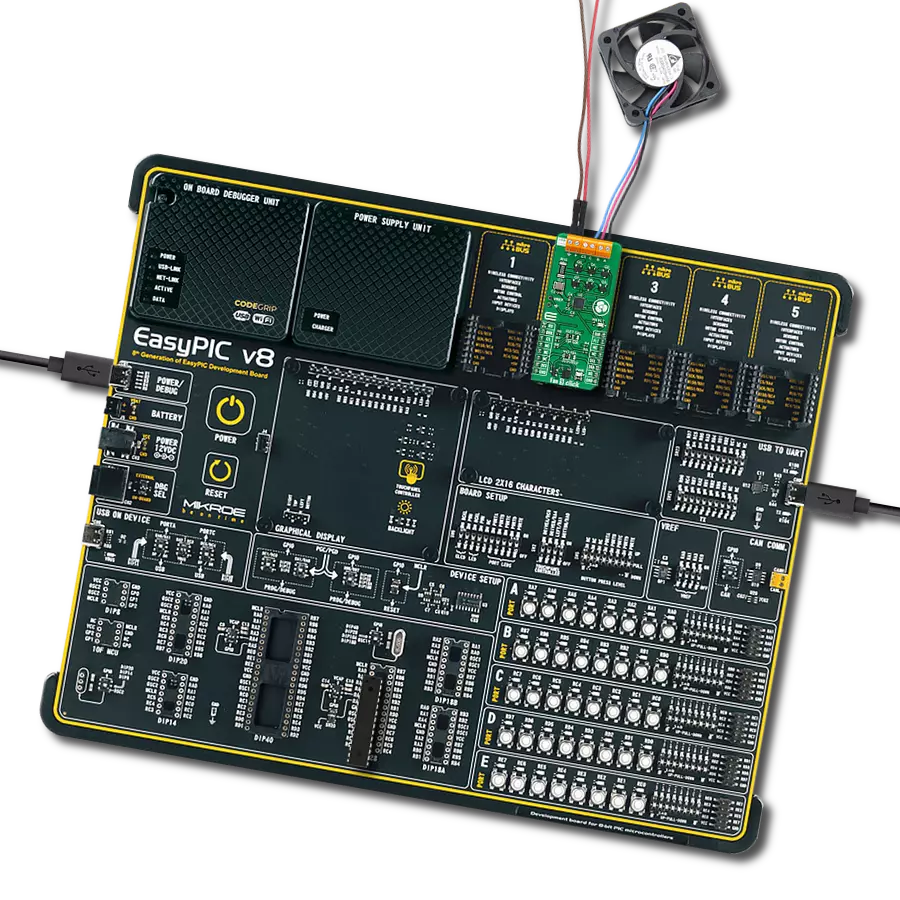
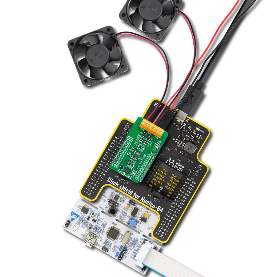
Fan 9 Click
Dev. board
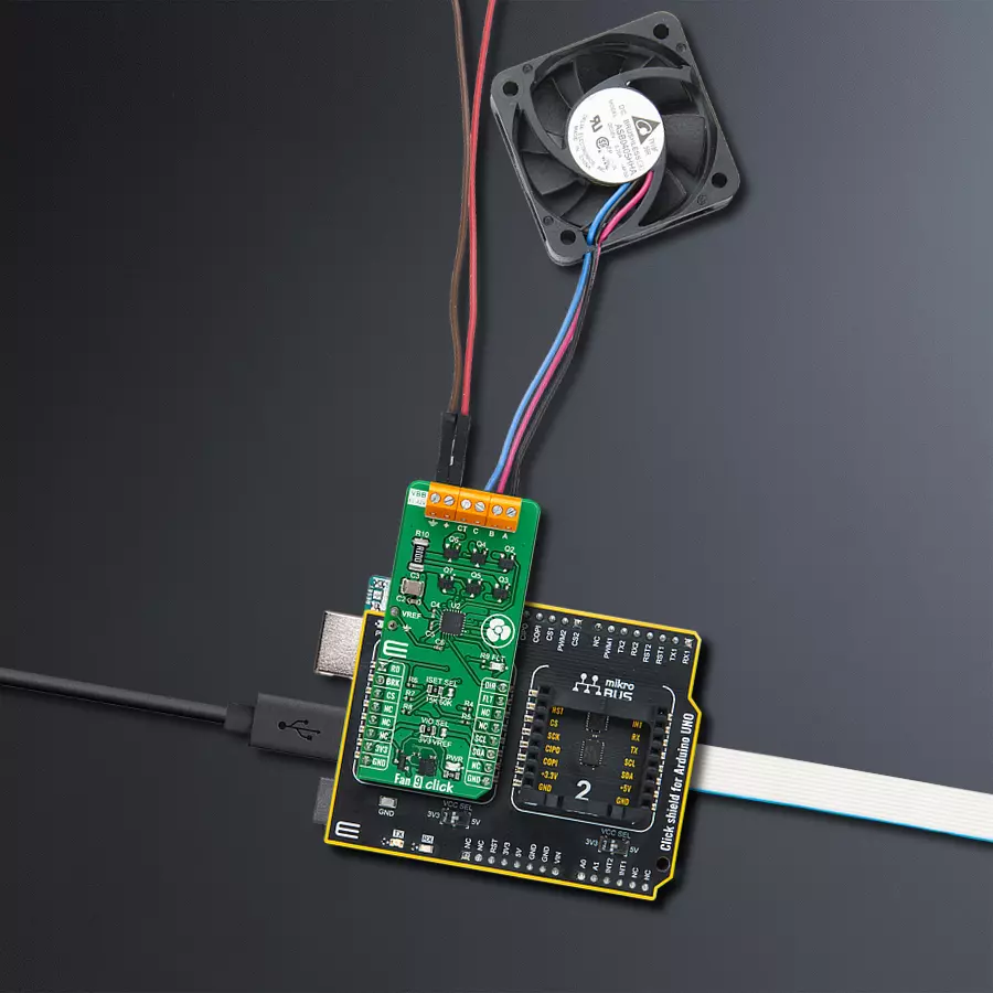
Arduino UNO Rev3
Compiler
NECTO Studio
MCU
ATmega328P
Perfect for high-power network equipment and industrial settings where efficient cooling is essential while maintaining quiet operation
A
A
Hardware Overview
How does it work?
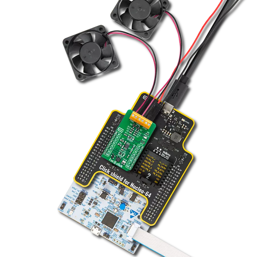
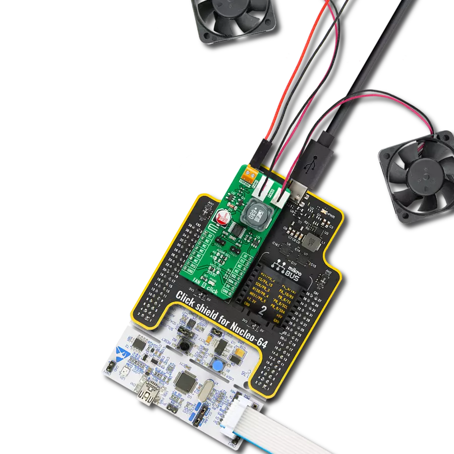
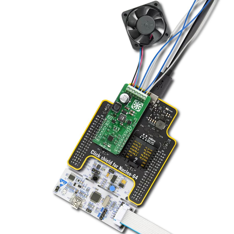
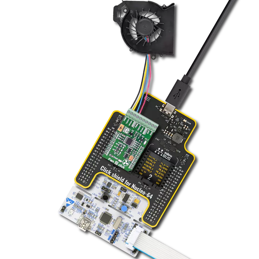
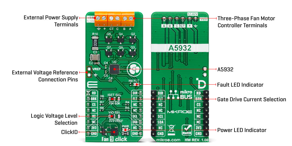
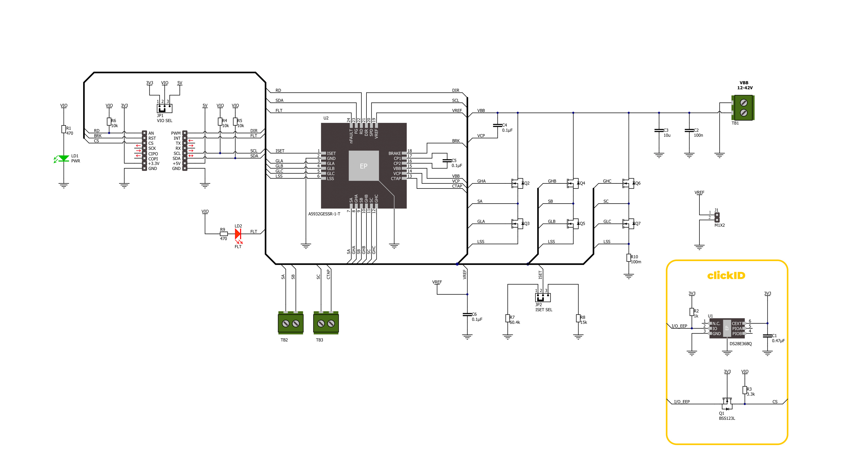
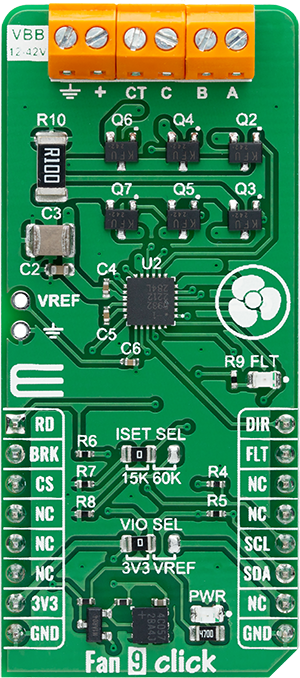
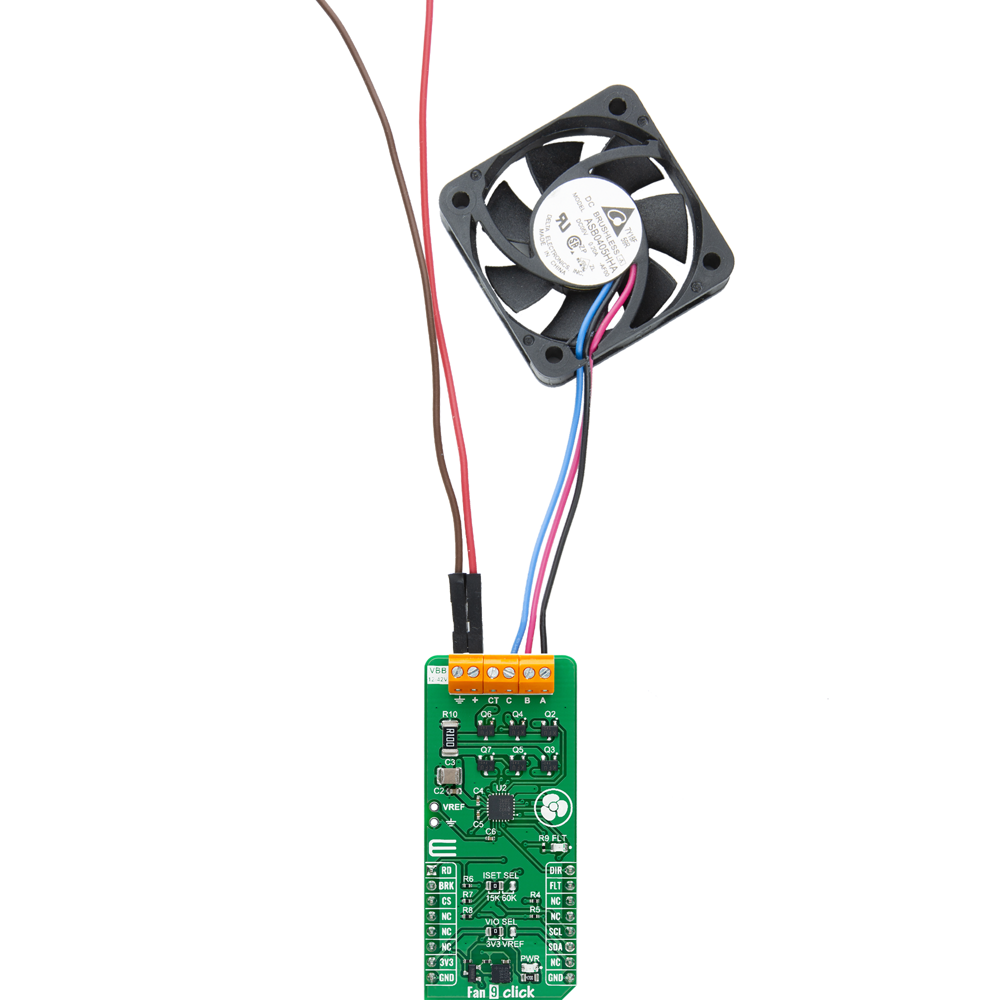
Fan 9 Click is based on the A5932, an automotive-grade (AEC-Q100 qualified) three-phase sinusoidal sensorless fan controller from Allegro Microsystems. The A5932 integrates sinusoidal drive technology to reduce audible noise and vibration, making it ideal for high-power fan applications. It operates with an external power supply ranging from 12V to 42V through the VBB terminal, targeting high-speed server fan applications to achieve low noise, minimal vibration, and high efficiency. Allegro's proprietary control algorithm optimizes efficiency across various speeds by adapting to different motor characteristics, resulting in a sinusoidal current waveform. The A5932 uses a standard fast-mode I2C interface with a clock frequency of 400kHz for programming the EEPROM or serially controlling the IC speed. The fan speed is controlled by a variable duty cycle PWM input via the SCL (SPD)
pin, and the SDA (FG) pin provides speed information to the host MCU as an open-drain output. Data transfer initiation does not require a special sequence. If the motor is running, the SDA pin may pull the data line LOW while initializing serial port mode. Sending an I2C command will turn off the motor, similar to receiving a 0% PWM duty command. Additionally, the board features an ISET SEL jumper for setting the gate current magnitude, offering a choice between 15K and 60K resistors, which correspond to approximately 30mA source current and 60mA sink current. Besides the I2C communication pins, successful control also involves the following mikroBUS™ pins: DIR for fan motor direction control, BRK for fan motor brake control, and RD as an open-drain speed output where a HIGH logic level indicates a rotor fault condition as defined by EEPROM variables. When disabled, the LOW to HIGH transition on the RD pin
signifies the end of the open-loop starting sequence. Additionally, a red FLT LED indicator signals fault conditions such as external power supply under/over-voltage, thermal shutdown, charge pump UVLO, overcurrent detection, and loss of synchronization (rotor lock detection). These conditions can also be tracked via the FLT mikroBUS™ pin. This Click board™ can operate with either 3.3V or an external connected voltage reference (2.8V brought to a VREF header unpopulated by default) as a logic voltage level selected via the VIO SEL jumper. The board must perform appropriate logic voltage level conversion before using MCUs with different logic levels. Also, it comes equipped with a library containing functions and an example code that can be used as a reference for further development.
Features overview
Development board
Arduino UNO is a versatile microcontroller board built around the ATmega328P chip. It offers extensive connectivity options for various projects, featuring 14 digital input/output pins, six of which are PWM-capable, along with six analog inputs. Its core components include a 16MHz ceramic resonator, a USB connection, a power jack, an
ICSP header, and a reset button, providing everything necessary to power and program the board. The Uno is ready to go, whether connected to a computer via USB or powered by an AC-to-DC adapter or battery. As the first USB Arduino board, it serves as the benchmark for the Arduino platform, with "Uno" symbolizing its status as the
first in a series. This name choice, meaning "one" in Italian, commemorates the launch of Arduino Software (IDE) 1.0. Initially introduced alongside version 1.0 of the Arduino Software (IDE), the Uno has since become the foundational model for subsequent Arduino releases, embodying the platform's evolution.

Microcontroller Overview
MCU Card / MCU

Architecture
AVR
MCU Memory (KB)
32
Silicon Vendor
Microchip
Pin count
28
RAM (Bytes)
2048
You complete me!
Accessories
Click Shield for Arduino UNO has two proprietary mikroBUS™ sockets, allowing all the Click board™ devices to be interfaced with the Arduino UNO board without effort. The Arduino Uno, a microcontroller board based on the ATmega328P, provides an affordable and flexible way for users to try out new concepts and build prototypes with the ATmega328P microcontroller from various combinations of performance, power consumption, and features. The Arduino Uno has 14 digital input/output pins (of which six can be used as PWM outputs), six analog inputs, a 16 MHz ceramic resonator (CSTCE16M0V53-R0), a USB connection, a power jack, an ICSP header, and reset button. Most of the ATmega328P microcontroller pins are brought to the IO pins on the left and right edge of the board, which are then connected to two existing mikroBUS™ sockets. This Click Shield also has several switches that perform functions such as selecting the logic levels of analog signals on mikroBUS™ sockets and selecting logic voltage levels of the mikroBUS™ sockets themselves. Besides, the user is offered the possibility of using any Click board™ with the help of existing bidirectional level-shifting voltage translators, regardless of whether the Click board™ operates at a 3.3V or 5V logic voltage level. Once you connect the Arduino UNO board with our Click Shield for Arduino UNO, you can access hundreds of Click boards™, working with 3.3V or 5V logic voltage levels.

Used MCU Pins
mikroBUS™ mapper
Take a closer look
Click board™ Schematic
Step by step
Project assembly

Start by selecting your development board and Click board™. Begin with the Arduino UNO Rev3 as your development board.


Track your results in real time
Application Output
1. Application Output - In Debug mode, the 'Application Output' window enables real-time data monitoring, offering direct insight into execution results. Ensure proper data display by configuring the environment correctly using the provided tutorial.

2. UART Terminal - Use the UART Terminal to monitor data transmission via a USB to UART converter, allowing direct communication between the Click board™ and your development system. Configure the baud rate and other serial settings according to your project's requirements to ensure proper functionality. For step-by-step setup instructions, refer to the provided tutorial.

3. Plot Output - The Plot feature offers a powerful way to visualize real-time sensor data, enabling trend analysis, debugging, and comparison of multiple data points. To set it up correctly, follow the provided tutorial, which includes a step-by-step example of using the Plot feature to display Click board™ readings. To use the Plot feature in your code, use the function: plot(*insert_graph_name*, variable_name);. This is a general format, and it is up to the user to replace 'insert_graph_name' with the actual graph name and 'variable_name' with the parameter to be displayed.

Software Support
Library Description
This library contains API for Fan 9 Click driver.
Key functions:
fan9_set_direction- This function is used to set direction of Fan 9 Click.fan9_write_reg- This function reads a data bytes from the selected register by using I2C serial interface.fan9_set_pwm- This function is used to get PWM value of Fan 9 Click.
Open Source
Code example
The complete application code and a ready-to-use project are available through the NECTO Studio Package Manager for direct installation in the NECTO Studio. The application code can also be found on the MIKROE GitHub account.
/*!
 * @file main.c
 * @brief Fan 9 Click example
 *
 * # Description
 * This example demonstrates the use of FAN 9 Click board,
 * by changing speed of the fan from 0 to 100 percent, then decreasing it back to 0.
 *
 * The demo application is composed of two sections :
 *
 * ## Application Init
 * Initializes the driver and performs the Click default configuration.
 *
 * ## Application Task
 * Changes the speed of fans by changing the PWM duty cycle.
 * The results are being displayed via USB UART where you can track their changes.
 *
 * @author Stefan Ilic
 *
 */

#include "board.h"
#include "log.h"
#include "fan9.h"

static fan9_t fan9;
static log_t logger;

void application_init ( void )
{
    log_cfg_t log_cfg;  /**< Logger config object. */
    fan9_cfg_t fan9_cfg;  /**< Click config object. */

    /**
     * Logger initialization.
     * Default baud rate: 115200
     * Default log level: LOG_LEVEL_DEBUG
     * @note If USB_UART_RX and USB_UART_TX
     * are defined as HAL_PIN_NC, you will
     * need to define them manually for log to work.
     * See @b LOG_MAP_USB_UART macro definition for detailed explanation.
     */
    LOG_MAP_USB_UART( log_cfg );
    log_init( &logger, &log_cfg );
    log_info( &logger, " Application Init " );

    // Click initialization.
    fan9_cfg_setup( &fan9_cfg );
    FAN9_MAP_MIKROBUS( fan9_cfg, MIKROBUS_1 );
    if ( I2C_MASTER_ERROR == fan9_init( &fan9, &fan9_cfg ) )
    {
        log_error( &logger, " Communication init." );
        for ( ; ; );
    }

    if ( FAN9_ERROR == fan9_default_cfg ( &fan9 ) )
    {
        log_error( &logger, " Default configuration." );
        for ( ; ; );
    }

    fan9_set_pwm( &fan9, 10 );
    // Waiting for motor to start.
    while ( 0 == fan9_get_rd_pin( &fan9 ) );

    log_info( &logger, " Application Task " );
}

void application_task ( void )
{
    static int8_t duty_cnt = 10;
    static int8_t duty_inc = 10;
    uint8_t direction = FAN9_DIRECTION_CW;

    fan9_set_pwm( &fan9, duty_cnt );
    log_printf( &logger, " Set PWM: %d%% \r\n", ( uint16_t ) duty_cnt );

    if ( 100 == duty_cnt )
    {
        duty_inc = -10;
    }
    else if ( 0 == duty_cnt )
    {
        duty_inc = 10;
    }
    duty_cnt += duty_inc;
    Delay_ms ( 1000 );
    Delay_ms ( 1000 );
}

int main ( void )
{
    /* Do not remove this line or clock might not be set correctly. */
    #ifdef PREINIT_SUPPORTED
    preinit();
    #endif

    application_init( );

    for ( ; ; )
    {
        application_task( );
    }

    return 0;
}

// ------------------------------------------------------------------------ END
Additional Support
Resources
Category:Brushless