Easily select and process analog signals from multiple sources with MAX4634 and ATmega328P
Switch to perfection

Published Feb 14, 2024
Click board™
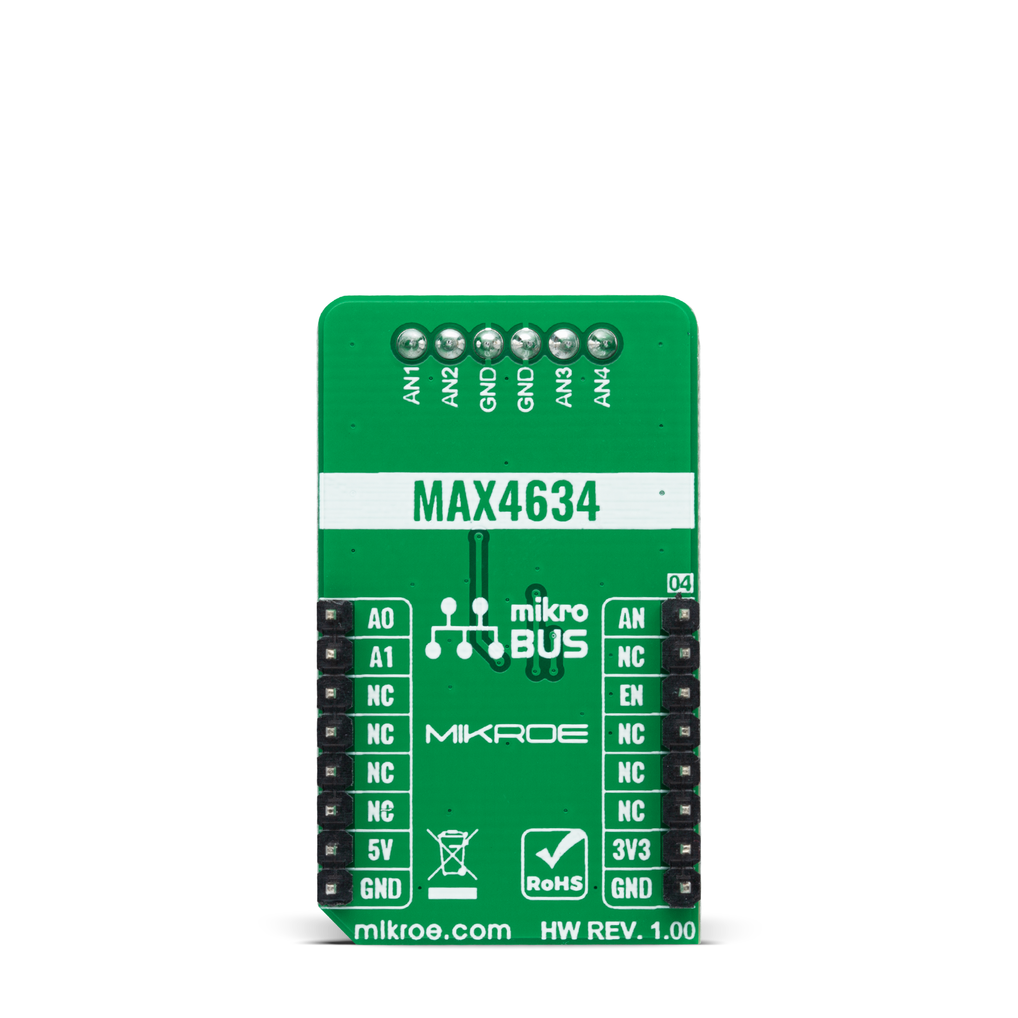
Analog MUX 5 Click
Dev. board
Arduino UNO Rev3
Compiler
NECTO Studio
MCU
ATmega328P
Experience the power of precise and low-voltage analog data switching for uncompromised audio, video, data-acquisition applications, and many more
A
A
Hardware Overview
How does it work?
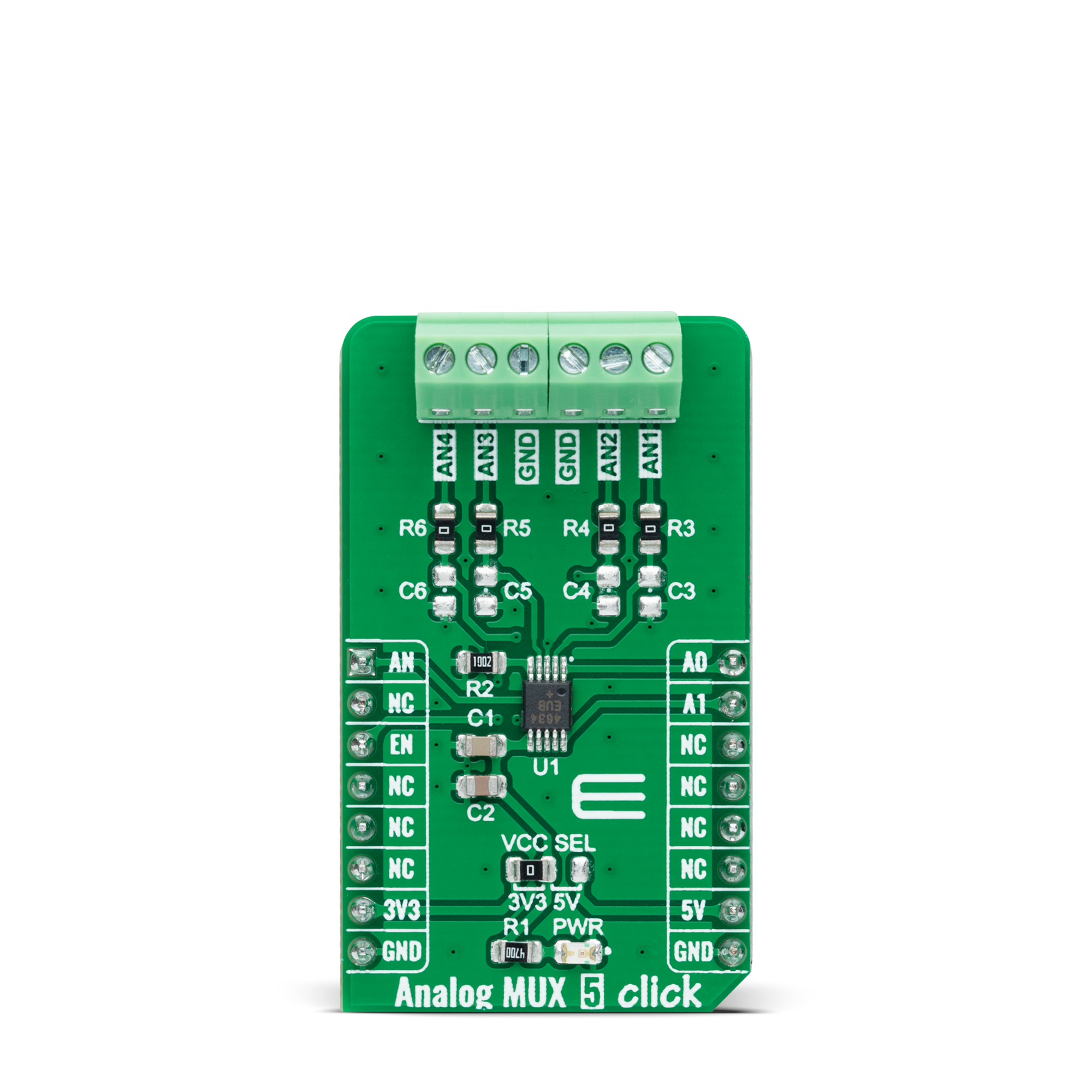
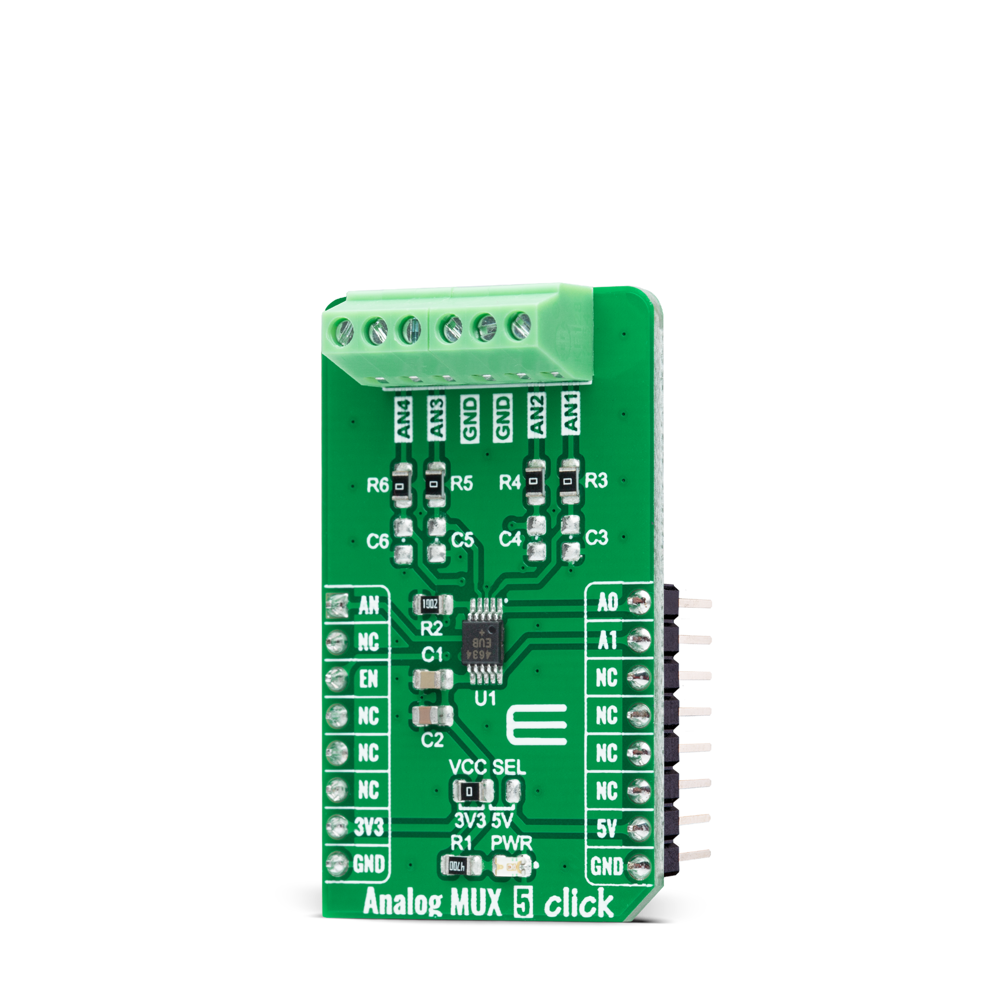
Analog MUX 5 Click is based on the MAX4634, a low-on-resistance, low-voltage analog multiplexer from Analog Devices. CMOS switch construction of the MAX4634 allows the processing of analog signals within its supply voltage range. It features 4Ω maximum ON-resistance (RON) and offers RON matching between switches to 0.3Ω maximum and RON flatness of 1Ω maximum over the specified signal range. Also, all digital inputs have +0.8V and +2.4V logic thresholds, ensuring TTL/CMOS-logic compatibility with +5V operation. This Click board™ communicates with MCU using several GPIO pins.
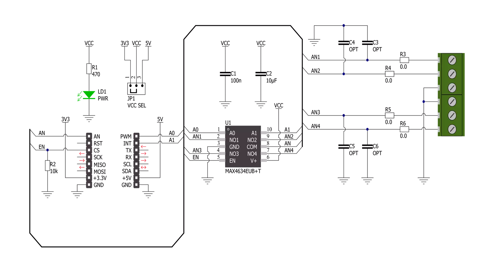
It can be enabled or disabled through the EN pin routed to the CS pin of the mikroBUS™ socket, hence, offering a switch operation to turn ON/OFF power delivery to the MAX4634. It also provides two address signals, labeled as A0 and A1 and routed to the PWM and INT pins of the mikroBUS™ socket, that determine the activation of the desired analog input channel based on their setup while monitoring of that input analog signal is done using AN pin of the mikroBUS™ socket. Each analog input has a jumper for its hardware activation or deactivation from R3 to R6 and capacitors for additional filtering of the input
channels from C3 to C6. Proper power-supply sequencing is recommended for all CMOS devices. Before applying analog signals or logic inputs, always apply the power supply first, especially if the analog or logic signals are not current-limited. This Click board™ can operate with either 3.3V or 5V logic voltage levels selected via the VCC SEL jumper. This way, both 3.3V and 5V capable MCUs can use the communication lines properly. However, the Click board™ comes equipped with a library containing easy-to-use functions and an example code that can be used, as a reference, for further development.
Features overview
Development board
Arduino UNO is a versatile microcontroller board built around the ATmega328P chip. It offers extensive connectivity options for various projects, featuring 14 digital input/output pins, six of which are PWM-capable, along with six analog inputs. Its core components include a 16MHz ceramic resonator, a USB connection, a power jack, an
ICSP header, and a reset button, providing everything necessary to power and program the board. The Uno is ready to go, whether connected to a computer via USB or powered by an AC-to-DC adapter or battery. As the first USB Arduino board, it serves as the benchmark for the Arduino platform, with "Uno" symbolizing its status as the
first in a series. This name choice, meaning "one" in Italian, commemorates the launch of Arduino Software (IDE) 1.0. Initially introduced alongside version 1.0 of the Arduino Software (IDE), the Uno has since become the foundational model for subsequent Arduino releases, embodying the platform's evolution.

Microcontroller Overview
MCU Card / MCU

Architecture
AVR
MCU Memory (KB)
32
Silicon Vendor
Microchip
Pin count
28
RAM (Bytes)
2048
You complete me!
Accessories
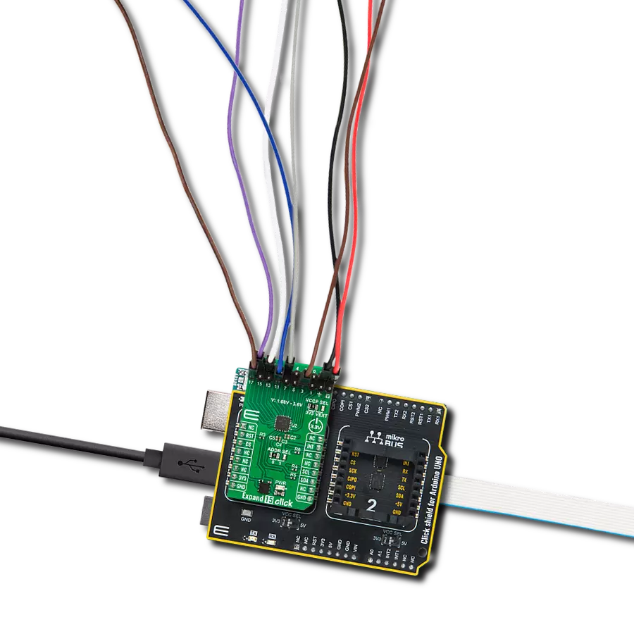
Click Shield for Arduino UNO has two proprietary mikroBUS™ sockets, allowing all the Click board™ devices to be interfaced with the Arduino UNO board without effort. The Arduino Uno, a microcontroller board based on the ATmega328P, provides an affordable and flexible way for users to try out new concepts and build prototypes with the ATmega328P microcontroller from various combinations of performance, power consumption, and features. The Arduino Uno has 14 digital input/output pins (of which six can be used as PWM outputs), six analog inputs, a 16 MHz ceramic resonator (CSTCE16M0V53-R0), a USB connection, a power jack, an ICSP header, and reset button. Most of the ATmega328P microcontroller pins are brought to the IO pins on the left and right edge of the board, which are then connected to two existing mikroBUS™ sockets. This Click Shield also has several switches that perform functions such as selecting the logic levels of analog signals on mikroBUS™ sockets and selecting logic voltage levels of the mikroBUS™ sockets themselves. Besides, the user is offered the possibility of using any Click board™ with the help of existing bidirectional level-shifting voltage translators, regardless of whether the Click board™ operates at a 3.3V or 5V logic voltage level. Once you connect the Arduino UNO board with our Click Shield for Arduino UNO, you can access hundreds of Click boards™, working with 3.3V or 5V logic voltage levels.

Used MCU Pins
mikroBUS™ mapper
Take a closer look
Click board™ Schematic
Step by step
Project assembly

Start by selecting your development board and Click board™. Begin with the Arduino UNO Rev3 as your development board.


Track your results in real time
Application Output
1. Application Output - In Debug mode, the 'Application Output' window enables real-time data monitoring, offering direct insight into execution results. Ensure proper data display by configuring the environment correctly using the provided tutorial.

2. UART Terminal - Use the UART Terminal to monitor data transmission via a USB to UART converter, allowing direct communication between the Click board™ and your development system. Configure the baud rate and other serial settings according to your project's requirements to ensure proper functionality. For step-by-step setup instructions, refer to the provided tutorial.

3. Plot Output - The Plot feature offers a powerful way to visualize real-time sensor data, enabling trend analysis, debugging, and comparison of multiple data points. To set it up correctly, follow the provided tutorial, which includes a step-by-step example of using the Plot feature to display Click board™ readings. To use the Plot feature in your code, use the function: plot(*insert_graph_name*, variable_name);. This is a general format, and it is up to the user to replace 'insert_graph_name' with the actual graph name and 'variable_name' with the parameter to be displayed.

Software Support
Library Description
This library contains API for Analog MUX 5 Click driver.
Key functions:
analogmux5_cfg_setup- Config Object Initialization function.analogmux5_init- Initialization function.analogmux5_default_cfg- Click Default Configuration function.
Open Source
Code example
The complete application code and a ready-to-use project are available through the NECTO Studio Package Manager for direct installation in the NECTO Studio. The application code can also be found on the MIKROE GitHub account.
/*!
 * @file main.c
 * @brief Analog MUX 5 Click Example.
 *
 * # Description
 * This example showcases how to initialize, configure and use the Analog MUX 5 Click module.
 *
 * The demo application is composed of two sections :
 *
 * ## Application Init
 * Initializes the driver and enables the analog inputs.
 *
 * ## Application Task
 * This is an example that shows the use of a Analog MUX 5 Click board.
 * In this example, we switch from channel AN1 to channel AN4,
 * read and display the voltage on the active channel.
 * Results are being sent to the Usart Terminal where you can track their changes.
 *
 *
 * @author Nikola Peric
 *
 */

#include "board.h"
#include "log.h"
#include "analogmux5.h"

static analogmux5_t analogmux5;   /**< Analog MUX 5 Click driver object. */
static log_t logger;              /**< Logger object. */

void application_init ( void )
{
    log_cfg_t log_cfg;                /**< Logger config object. */
    analogmux5_cfg_t analogmux5_cfg;  /**< Click config object. */

    /**
     * Logger initialization.
     * Default baud rate: 115200
     * Default log level: LOG_LEVEL_DEBUG
     * @note If USB_UART_RX and USB_UART_TX
     * are defined as HAL_PIN_NC, you will
     * need to define them manually for log to work.
     * See @b LOG_MAP_USB_UART macro definition for detailed explanation.
     */
    LOG_MAP_USB_UART( log_cfg );
    log_init( &logger, &log_cfg );
    log_info( &logger, " Application Init " );

    // Click initialization.
    analogmux5_cfg_setup( &analogmux5_cfg );
    ANALOGMUX5_MAP_MIKROBUS( analogmux5_cfg, MIKROBUS_1 );
    if ( ADC_ERROR == analogmux5_init( &analogmux5, &analogmux5_cfg ) )
    {
        log_error( &logger, " Communication init." );
        for ( ; ; );
    }

    if ( ANALOGMUX5_ERROR == analogmux5_default_cfg ( &analogmux5 ) )
    {
        log_error( &logger, " Default configuration." );
        for ( ; ; );
    }

    log_info( &logger, " Application Task " );
}

void application_task ( void )
{
    float analogmux5_an_voltage = 0;

    analogmux5_select_ch( &analogmux5, ANALOGMUX5_SEL_CH_1 );
    Delay_ms ( 100 );

    if ( ADC_ERROR != analogmux5_read_an_pin_voltage ( &analogmux5, &analogmux5_an_voltage ) )
    {
        log_printf( &logger, " Channel [ 1 ] ---> AN Voltage : %.3f[V]\r\n\n", analogmux5_an_voltage );
    }

    analogmux5_select_ch( &analogmux5, ANALOGMUX5_SEL_CH_2 );
    Delay_ms ( 100 );

    if ( ADC_ERROR != analogmux5_read_an_pin_voltage ( &analogmux5, &analogmux5_an_voltage ) )
    {
        log_printf( &logger, " Channel [ 2 ] ---> AN Voltage : %.3f[V]\r\n\n", analogmux5_an_voltage );
    }

    analogmux5_select_ch( &analogmux5, ANALOGMUX5_SEL_CH_3 );
    Delay_ms ( 100 );

    if ( ADC_ERROR != analogmux5_read_an_pin_voltage ( &analogmux5, &analogmux5_an_voltage ) )
    {
        log_printf( &logger, " Channel [ 3 ] ---> AN Voltage : %.3f[V]\r\n\n", analogmux5_an_voltage );
    }

    analogmux5_select_ch( &analogmux5, ANALOGMUX5_SEL_CH_4 );
    Delay_ms ( 100 );

    if ( ADC_ERROR != analogmux5_read_an_pin_voltage ( &analogmux5, &analogmux5_an_voltage ) )
    {
        log_printf( &logger, " Channel [ 4 ] ---> AN Voltage : %.3f[V]\r\n\n", analogmux5_an_voltage );
    }
    Delay_ms ( 1000 );
}

int main ( void )
{
    /* Do not remove this line or clock might not be set correctly. */
    #ifdef PREINIT_SUPPORTED
    preinit();
    #endif

    application_init( );

    for ( ; ; )
    {
        application_task( );
    }

    return 0;
}

// ------------------------------------------------------------------------ END
Additional Support
Resources
Category:Port expander