Measure a broad spectrum of air pressures in the surrounding environment with BMP585 and ATmega328P
Attain accurate readings across different pressures and temperatures

Published Feb 14, 2024
Click board™
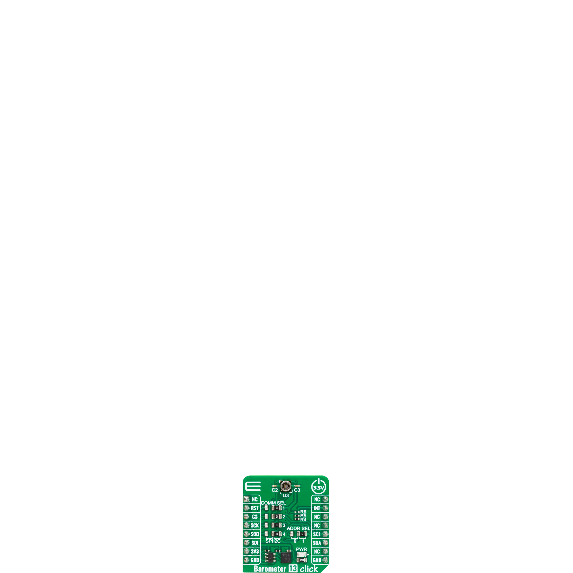
Barometer 13 Click
Dev. board
Arduino UNO Rev3
Compiler
NECTO Studio
MCU
ATmega328P
Upgrade your project capabilities with precise air pressure measurements across various environments, perfect for applications like weather monitoring, portable devices, and immersive virtual experiences
A
A
Hardware Overview
How does it work?
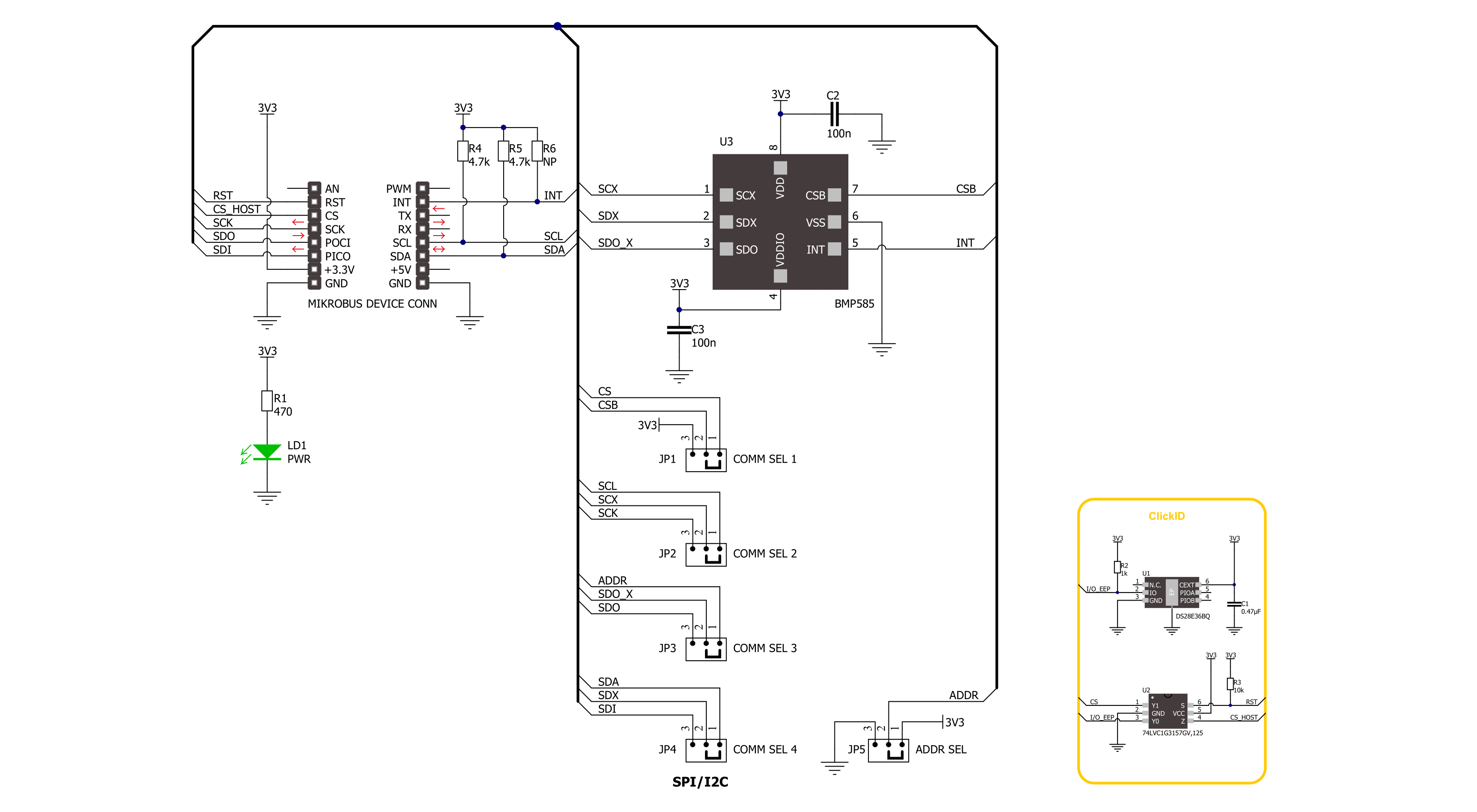
Barometer 13 Click is based on the BMP585, a barometric pressure sensor from Bosch Sensortec. It consists of a pressure-sensitive MEMS sensor element and an integrated circuit that drives and reads out the sensor element. The on-chip FIFO buffer can hold up to 32 pressure samples with an absolute pressure accuracy of ±30Pa. The sensor itself can work in normal, forced, and continuous modes, while in standby mode, no measurements are performed, and power consumption is at a minimum. There is also a deep standby mode with
further reduced power consumption. The BMP585 has a built-in dedicated IIR filter that can reduce noise caused by ambient disturbances, such as an open window, door, and more. Barometer 13 Click can use a standard 2-wire I2C interface to communicate with the host MCU, with a clock frequency of up to 1MHz. The I2C address can be selected over the ADDR SEL jumper. You can also use a standard 4-wire SPI interface for the same purpose, with a clock frequency of up to 12MHz. The selection can be made over the COMM SEL
jumpers. The BMP585 provides an interrupt functionality, which allows it to signal certain events to the host processor over the INT pin. This Click board™ can be operated only with a 3.3V logic voltage level. The board must perform appropriate logic voltage level conversion before using MCUs with different logic levels. Also, it comes equipped with a library containing functions and an example code that can be used as a reference for further development.

Features overview
Development board
Arduino UNO is a versatile microcontroller board built around the ATmega328P chip. It offers extensive connectivity options for various projects, featuring 14 digital input/output pins, six of which are PWM-capable, along with six analog inputs. Its core components include a 16MHz ceramic resonator, a USB connection, a power jack, an
ICSP header, and a reset button, providing everything necessary to power and program the board. The Uno is ready to go, whether connected to a computer via USB or powered by an AC-to-DC adapter or battery. As the first USB Arduino board, it serves as the benchmark for the Arduino platform, with "Uno" symbolizing its status as the
first in a series. This name choice, meaning "one" in Italian, commemorates the launch of Arduino Software (IDE) 1.0. Initially introduced alongside version 1.0 of the Arduino Software (IDE), the Uno has since become the foundational model for subsequent Arduino releases, embodying the platform's evolution.

Microcontroller Overview
MCU Card / MCU

Architecture
AVR
MCU Memory (KB)
32
Silicon Vendor
Microchip
Pin count
28
RAM (Bytes)
2048
You complete me!
Accessories
Click Shield for Arduino UNO has two proprietary mikroBUS™ sockets, allowing all the Click board™ devices to be interfaced with the Arduino UNO board without effort. The Arduino Uno, a microcontroller board based on the ATmega328P, provides an affordable and flexible way for users to try out new concepts and build prototypes with the ATmega328P microcontroller from various combinations of performance, power consumption, and features. The Arduino Uno has 14 digital input/output pins (of which six can be used as PWM outputs), six analog inputs, a 16 MHz ceramic resonator (CSTCE16M0V53-R0), a USB connection, a power jack, an ICSP header, and reset button. Most of the ATmega328P microcontroller pins are brought to the IO pins on the left and right edge of the board, which are then connected to two existing mikroBUS™ sockets. This Click Shield also has several switches that perform functions such as selecting the logic levels of analog signals on mikroBUS™ sockets and selecting logic voltage levels of the mikroBUS™ sockets themselves. Besides, the user is offered the possibility of using any Click board™ with the help of existing bidirectional level-shifting voltage translators, regardless of whether the Click board™ operates at a 3.3V or 5V logic voltage level. Once you connect the Arduino UNO board with our Click Shield for Arduino UNO, you can access hundreds of Click boards™, working with 3.3V or 5V logic voltage levels.

Used MCU Pins
mikroBUS™ mapper
Take a closer look
Click board™ Schematic
Step by step
Project assembly

Start by selecting your development board and Click board™. Begin with the Arduino UNO Rev3 as your development board.


Track your results in real time
Application Output
1. Application Output - In Debug mode, the 'Application Output' window enables real-time data monitoring, offering direct insight into execution results. Ensure proper data display by configuring the environment correctly using the provided tutorial.

2. UART Terminal - Use the UART Terminal to monitor data transmission via a USB to UART converter, allowing direct communication between the Click board™ and your development system. Configure the baud rate and other serial settings according to your project's requirements to ensure proper functionality. For step-by-step setup instructions, refer to the provided tutorial.

3. Plot Output - The Plot feature offers a powerful way to visualize real-time sensor data, enabling trend analysis, debugging, and comparison of multiple data points. To set it up correctly, follow the provided tutorial, which includes a step-by-step example of using the Plot feature to display Click board™ readings. To use the Plot feature in your code, use the function: plot(*insert_graph_name*, variable_name);. This is a general format, and it is up to the user to replace 'insert_graph_name' with the actual graph name and 'variable_name' with the parameter to be displayed.

Software Support
Library Description
This library contains API for Barometer 13 Click driver.
Key functions:
barometer13_get_measurement_data- Barometer 13 get the measurement data functionbarometer13_set_odr- Barometer 13 set the output data rate functionbarometer13_set_int_cfg- Barometer 13 set the interrupt config function
Open Source
Code example
The complete application code and a ready-to-use project are available through the NECTO Studio Package Manager for direct installation in the NECTO Studio. The application code can also be found on the MIKROE GitHub account.
/*!
 * @file main.c
 * @brief Barometer 13 Click example
 *
 * # Description
 * This example demonstrates the use of  Barometer 13  Click board™
 * by reading and displaying the pressure and temperature measurements.
 *
 * The demo application is composed of two sections :
 *
 * ## Application Init
 * The initialization of I2C or SPI module and log UART.
 * After driver initialization, the app sets the default configuration.
 *
 * ## Application Task
 * The demo application reads and displays the Pressure [mBar] and Temperature [degree Celsius] data.
 * Results are being sent to the UART Terminal, where you can track their changes.
 *
 * @author Nenad Filipovic
 *
 */

#include "board.h"
#include "log.h"
#include "barometer13.h"

static barometer13_t barometer13;
static log_t logger;

void application_init ( void )
{
    log_cfg_t log_cfg;  /**< Logger config object. */
    barometer13_cfg_t barometer13_cfg;  /**< Click config object. */

    /**
     * Logger initialization.
     * Default baud rate: 115200
     * Default log level: LOG_LEVEL_DEBUG
     * @note If USB_UART_RX and USB_UART_TX
     * are defined as HAL_PIN_NC, you will
     * need to define them manually for log to work.
     * See @b LOG_MAP_USB_UART macro definition for detailed explanation.
     */
    LOG_MAP_USB_UART( log_cfg );
    log_init( &logger, &log_cfg );
    log_info( &logger, " Application Init " );

    // Click initialization.
    barometer13_cfg_setup( &barometer13_cfg );
    BAROMETER13_MAP_MIKROBUS( barometer13_cfg, MIKROBUS_1 );
    err_t init_flag = barometer13_init( &barometer13, &barometer13_cfg );
    if ( ( I2C_MASTER_ERROR == init_flag ) || ( SPI_MASTER_ERROR == init_flag ) )
    {
        log_error( &logger, " Communication init." );
        for ( ; ; );
    }

    if ( BAROMETER13_ERROR == barometer13_default_cfg ( &barometer13 ) )
    {
        log_error( &logger, " Default configuration." );
        for ( ; ; );
    }

    log_info( &logger, " Application Task " );
    log_printf( &logger, " ______________________ \r\n" );
}

void application_task ( void )
{
    float pressure = 0, temperature = 0;
    if ( ( BAROMETER13_OK == barometer13_get_measurement( &barometer13, &pressure, &temperature ) ) &&
         barometer13_get_interrupt( &barometer13 ) )
    {
        log_printf( &logger, " Pressure    : %.2f mBar \r\n", pressure );
        log_printf( &logger, " Temperature : %.2f degC \r\n", temperature );
        log_printf( &logger, " ______________________ \r\n" );
        Delay_ms ( 1000 );
    }
}

int main ( void )
{
    /* Do not remove this line or clock might not be set correctly. */
    #ifdef PREINIT_SUPPORTED
    preinit();
    #endif

    application_init( );

    for ( ; ; )
    {
        application_task( );
    }

    return 0;
}

// ------------------------------------------------------------------------ END
Additional Support
Resources
Category:Pressure


