Accurately detect and analyze colors with VEML6040 and ATmega328P
Color excellence at your fingertips

Published Feb 14, 2024
Click board™
Color 4 Click
Dev. board
Arduino UNO Rev3
Compiler
NECTO Studio
MCU
ATmega328P
Improve efficiency and accuracy in color-related tasks, from design and manufacturing to diagnostics and beyond.
A
A
Hardware Overview
How does it work?
Color 4 Click is based on the VEML6040, an advanced RGB/ambient light sensor from Vishay Semiconductors that provides fast and accurate spectral measurements. It is based on the Filtron™ technology, achieving the closest ambient light spectral sensitivity to real-human eye responses. The VEML6040 senses red, green, blue, and white light and processes those signals using a CMOS signal conditioning circuit. This digital RGBW information can be used in feedback control systems, among other things, to monitor and actively control a light source. This Click board™ detects light intensity under multiple lighting
conditions and through different attenuation materials, including dark glass. The VEML6040 provides a selectable measurement range from 515.4lx up to 16.496lx with the highest sensitivity of 0.007865lx/step. Its peak sensitivities for red, green, and blue are 645nm, 575nm, and 460nm, respectively. Moreover, it provides excellent temperature compensation, keeping the output stable under changing temperatures. Color 4 Click communicates with MCU using the standard I2C 2-Wire interface to read data and configure settings, supporting Standard Mode operation with a clock frequency of 100kHz and Fast Mode
up to 400kHz. The VEML6040 contains one configuration register (00h) for operation control and parameter setup. Its measurement results are stored in four separate registers, each for red, green, blue, and white, with addresses from 08h to 0Bh, respectively. All registers are 16-bit wide. This Click board™ can be operated only with a 3.3V logic voltage level. The board must perform appropriate logic voltage level conversion before using MCUs with different logic levels. Also, it comes equipped with a library containing functions and an example code that can be used as a reference for further development.


Features overview
Development board
Arduino UNO is a versatile microcontroller board built around the ATmega328P chip. It offers extensive connectivity options for various projects, featuring 14 digital input/output pins, six of which are PWM-capable, along with six analog inputs. Its core components include a 16MHz ceramic resonator, a USB connection, a power jack, an
ICSP header, and a reset button, providing everything necessary to power and program the board. The Uno is ready to go, whether connected to a computer via USB or powered by an AC-to-DC adapter or battery. As the first USB Arduino board, it serves as the benchmark for the Arduino platform, with "Uno" symbolizing its status as the
first in a series. This name choice, meaning "one" in Italian, commemorates the launch of Arduino Software (IDE) 1.0. Initially introduced alongside version 1.0 of the Arduino Software (IDE), the Uno has since become the foundational model for subsequent Arduino releases, embodying the platform's evolution.

Microcontroller Overview
MCU Card / MCU

Architecture
AVR
MCU Memory (KB)
32
Silicon Vendor
Microchip
Pin count
28
RAM (Bytes)
2048
You complete me!
Accessories
Click Shield for Arduino UNO has two proprietary mikroBUS™ sockets, allowing all the Click board™ devices to be interfaced with the Arduino UNO board without effort. The Arduino Uno, a microcontroller board based on the ATmega328P, provides an affordable and flexible way for users to try out new concepts and build prototypes with the ATmega328P microcontroller from various combinations of performance, power consumption, and features. The Arduino Uno has 14 digital input/output pins (of which six can be used as PWM outputs), six analog inputs, a 16 MHz ceramic resonator (CSTCE16M0V53-R0), a USB connection, a power jack, an ICSP header, and reset button. Most of the ATmega328P microcontroller pins are brought to the IO pins on the left and right edge of the board, which are then connected to two existing mikroBUS™ sockets. This Click Shield also has several switches that perform functions such as selecting the logic levels of analog signals on mikroBUS™ sockets and selecting logic voltage levels of the mikroBUS™ sockets themselves. Besides, the user is offered the possibility of using any Click board™ with the help of existing bidirectional level-shifting voltage translators, regardless of whether the Click board™ operates at a 3.3V or 5V logic voltage level. Once you connect the Arduino UNO board with our Click Shield for Arduino UNO, you can access hundreds of Click boards™, working with 3.3V or 5V logic voltage levels.

Used MCU Pins
mikroBUS™ mapper
Take a closer look
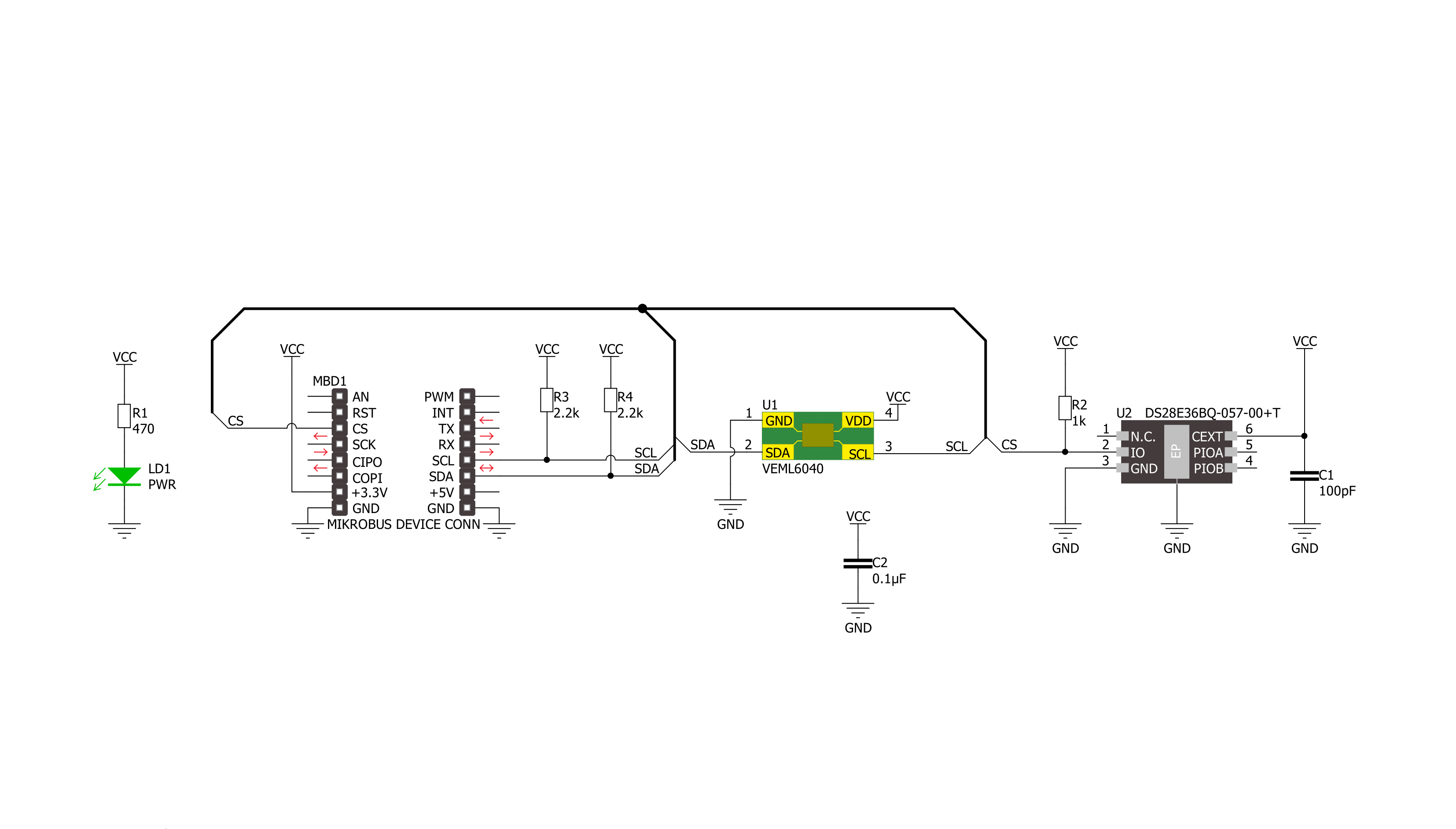
Click board™ Schematic
Step by step
Project assembly

Start by selecting your development board and Click board™. Begin with the Arduino UNO Rev3 as your development board.


Track your results in real time
Application Output
1. Application Output - In Debug mode, the 'Application Output' window enables real-time data monitoring, offering direct insight into execution results. Ensure proper data display by configuring the environment correctly using the provided tutorial.

2. UART Terminal - Use the UART Terminal to monitor data transmission via a USB to UART converter, allowing direct communication between the Click board™ and your development system. Configure the baud rate and other serial settings according to your project's requirements to ensure proper functionality. For step-by-step setup instructions, refer to the provided tutorial.

3. Plot Output - The Plot feature offers a powerful way to visualize real-time sensor data, enabling trend analysis, debugging, and comparison of multiple data points. To set it up correctly, follow the provided tutorial, which includes a step-by-step example of using the Plot feature to display Click board™ readings. To use the Plot feature in your code, use the function: plot(*insert_graph_name*, variable_name);. This is a general format, and it is up to the user to replace 'insert_graph_name' with the actual graph name and 'variable_name' with the parameter to be displayed.

Software Support
Library Description
This library contains API for Color 4 Click driver.
Key functions:
color4_set_config- Color 4 set configuration functioncolor4_get_color_data- Color 4 get color data functioncolor4_get_ambient_light- Color 4 get ambient light level function
Open Source
Code example
The complete application code and a ready-to-use project are available through the NECTO Studio Package Manager for direct installation in the NECTO Studio. The application code can also be found on the MIKROE GitHub account.
/*!
 * @file main.c
 * @brief Color 4 Click example
 *
 * # Description
 * This library contains API for the Color 4 Click driver.
 * This driver provides the functions for the sensor configuration
 * and for reading RGBW and ambient light data from the device.
 * This example displays RGBW data, Ambient light level, CCT data
 * and the light color names.
 *
 * The demo application is composed of two sections :
 *
 * ## Application Init
 * Initialization of I2C module and log UART.
 * After driver initialization, default settings turn on the device.
 *
 * ## Application Task
 * This example demonstrates the use of the Color 4 Click board™.
 * Reads and displays the results of the RGBW, Ambient light level,
 * calculate the correlated color temperature.
 * This example also detects and displays the light color names.
 * Results are being sent to the UART Terminal, where you can track their changes.
 *
 * @note
 * Color detection is obtained based on the analysis
 * of calculate the correlated color temperature (CCT) data
 * and the CIE 1931 chromaticity diagram.
 * For more details please refer to the “Designing the VEML6040 into an Application”
 * application note (www.vishay.com/doc?84331).
 *
 * @author Nenad Filipovic
 *
 */

#include "board.h"
#include "log.h"
#include "color4.h"

#define COLOR4_LIM_WHITE_COLOR        17000
#define COLOR4_LIM_DARK_LUX           15.0
#define COLOR4_CCT_LIM_BLUE_COLOR     9000
#define COLOR4_CCT_LIM_PURPLE_COLOR   7500
#define COLOR4_CCT_LIM_GREEN_COLOR    6000
#define COLOR4_CCT_LIM_YELLOW_COLOR   3500
#define COLOR4_CCT_LIM_ORANGE_COLOR   2200
#define COLOR4_CCT_LIM_PINK_COLOR     1900
#define COLOR4_CCT_LIM_RED_COLOR      700

static color4_t color4;
static log_t logger;
static uint16_t red_data, green_data, blue_data, white_data;
static float ambient_light, cct;

void display_color ( void )
{
    if ( ambient_light < COLOR4_LIM_DARK_LUX )
    {
        log_printf( &logger, " Color DARK\r\n", cct );
    }
    else if ( white_data > COLOR4_LIM_WHITE_COLOR )
    {
        log_printf( &logger, " Color WHITE\r\n", cct );
    }
    else if ( cct > COLOR4_CCT_LIM_BLUE_COLOR  )
    {
        log_printf( &logger, " Color BLUE\r\n", cct );
    }
    else if ( cct > COLOR4_CCT_LIM_PURPLE_COLOR )
    {
        log_printf( &logger, " Color PURPLE\r\n", cct );
    }
    else if ( cct > COLOR4_CCT_LIM_GREEN_COLOR )
    {
        log_printf( &logger, " Color GREEN\r\n", cct );
    }
    else if ( cct > COLOR4_CCT_LIM_YELLOW_COLOR )
    {
        log_printf( &logger, " Color YELLOW\r\n", cct );
    }
    else if ( cct > COLOR4_CCT_LIM_ORANGE_COLOR )
    {
        log_printf( &logger, " Color ORANGE\r\n", cct );
    }
    else if ( cct > COLOR4_CCT_LIM_PINK_COLOR )
    {
        log_printf( &logger, " Color PINK\r\n", cct );
    }
    else if ( cct > COLOR4_CCT_LIM_RED_COLOR )
    {
        log_printf( &logger, " Color RED\r\n", cct );
    }
    else
    {
        log_printf( &logger, " Color BLUE\r\n", cct );
    }
}

void application_init ( void )
{
    log_cfg_t log_cfg;  /**< Logger config object. */
    color4_cfg_t color4_cfg;  /**< Click config object. */

    /**
     * Logger initialization.
     * Default baud rate: 115200
     * Default log level: LOG_LEVEL_DEBUG
     * @note If USB_UART_RX and USB_UART_TX
     * are defined as HAL_PIN_NC, you will
     * need to define them manually for log to work.
     * See @b LOG_MAP_USB_UART macro definition for detailed explanation.
     */
    LOG_MAP_USB_UART( log_cfg );
    log_init( &logger, &log_cfg );
    log_info( &logger, " Application Init " );

    // Click initialization.
    color4_cfg_setup( &color4_cfg );
    COLOR4_MAP_MIKROBUS( color4_cfg, MIKROBUS_1 );
    if ( I2C_MASTER_ERROR == color4_init( &color4, &color4_cfg ) )
    {
        log_error( &logger, " Communication init." );
        for ( ; ; );
    }

    if ( COLOR4_ERROR == color4_default_cfg ( &color4 ) )
    {
        log_error( &logger, " Default configuration." );
        for ( ; ; );
    }

    log_info( &logger, " Application Task " );
    log_printf( &logger, " ----------------------\r\n" );
    Delay_ms ( 100 );
}

void application_task ( void )
{
    if ( COLOR4_OK == color4_get_color_data( &color4, COLOR4_RED, &red_data ) )
    {
        log_printf( &logger, " Red: %u\r\n", red_data );
    }

    if ( COLOR4_OK == color4_get_color_data( &color4, COLOR4_GREEN, &green_data ) )
    {
        log_printf( &logger, " Green: %u\r\n", green_data );
    }

    if ( COLOR4_OK == color4_get_color_data( &color4, COLOR4_BLUE, &blue_data ) )
    {
        log_printf( &logger, " Blue: %u\r\n", blue_data );
    }

    if ( COLOR4_OK == color4_get_color_data( &color4, COLOR4_WHITE, &white_data ) )
    {
        log_printf( &logger, " White: %u\r\n", white_data );
    }
    log_printf( &logger, " - - - - - - -  - - - - \r\n" );

    if ( COLOR4_OK == color4_get_ambient_light( &color4, &ambient_light ) )
    {
        log_printf( &logger, " ALS lux level: %.2f\r\n", ambient_light );
    }

    if ( COLOR4_OK == color4_get_cct( &color4, &cct ) )
    {
        log_printf( &logger, " CCT: %.2f\r\n", cct );
    }
    log_printf( &logger, " - - - - - - -  - - - - \r\n" );

    display_color( );
    log_printf( &logger, " ----------------------\r\n" );
    Delay_ms ( 1000 );
}

int main ( void )
{
    /* Do not remove this line or clock might not be set correctly. */
    #ifdef PREINIT_SUPPORTED
    preinit();
    #endif

    application_init( );

    for ( ; ; )
    {
        application_task( );
    }

    return 0;
}

// ------------------------------------------------------------------------ END
Additional Support
Resources
Category:Optical


