Set a new standard for accurate and reliable real-time distance insights using AFBR-S50 and STM32F031K6
ToF technology that paves the way for precise distance metrics

Published Oct 01, 2024
Click board™
LightRanger 7 Click
Dev. board
Nucleo 32 with STM32F031K6 MCU
Compiler
NECTO Studio
MCU
STM32F031K6
Designed with a dedication to excellence, this ToF distance measurement solution aims to be the cornerstone of innovation in fields where precision matters most, setting a new benchmark for reliable and instantaneous distance metrics
A
A
Hardware Overview
How does it work?
LightRanger 7 Click is based on the AFBR-S50, a multi-pixel optical distance and motion measurement sensor module based on the Time-of-Flight principle from Broadcom. The AFBR-S50 is developed with a particular focus on applications with the need for the highest speed and accuracy at medium distance ranges with low power consumption. Due to its best-in-class ambient light suppression, use in outside environments is possible in direct sunlight and on white, black, colored, metallic, and retroreflective surfaces. This feature makes it suitable for optical distance measurements requiring precise 3D information and extended range like drones or AMR/AGV. This board represents an integrated solution consisting of a 32-bit MCU, RA4M2 group of Renesas MCU with Arm® Cortex®-M33 core, and a ToF sensor with an integrated infrared laser light source mounted on a compact-sized PCB. In addition to an SPI-compatible interface for data transferring to the RA4M2 MCU, the AFBR-S50 also has an interrupt
line through which the MCU can register the data-ready event. Also, such conditions and other interrupts can be visually represented using the yellow LED indicator marked with STATUS. The RA4M2 interfaces with a host MCU through UART communication via commonly used RX and TX mikorBUS™ pins. Since the AFBR-S50 is known to be used in both robotics and drones, it is essential to note that this ToF sensor is compatible with Pixhawk®, a popular general-purpose flight controller, accessible via two 4-pin CAN connectors, J1 and J2, and controllable through onboard CAN controller, the MCP2542WFD from Microchip. Also, there is a clear visual indication of the execution of the communication itself; more precisely, the user can catch the operation of CAN communication/signal transfer via orange LED indicators provided for indication of received and transmitted CAN signals. In addition, this board also offers complete debugging and programming capabilities supported through an additional header
marked with J3. With this header, the user can use a Serial Wire Debug interface for programming and debugging, available through the SWD interface pins. Besides, it also has a Micro B USB connector, allowing the board to be powered and configured by a personal computer (PC). This way, it is possible to flash the AFBR-S50 ToF sensor via bootloader. This Click board™ uses both mikroBUS™ power rails, 3.3V and 5V. 5V is necessary to power the ToF sensor, while all unnecessary communication and data transfer is done using 3.3V logic. Thanks to the onboard LDO regulator, the SPX3819, even in the standalone CAN configuration, both voltages are provided: 5V through the CAN connector, while the regulator creates a voltage of 3.3V essential for the proper operation of the MCU. Also, this Click board™ comes equipped with a library containing easy-to-use functions and an example code that can be used as a reference for further development.

Features overview
Development board
Nucleo 32 with STM32F031K6 MCU board provides an affordable and flexible platform for experimenting with STM32 microcontrollers in 32-pin packages. Featuring Arduino™ Nano connectivity, it allows easy expansion with specialized shields, while being mbed-enabled for seamless integration with online resources. The
board includes an on-board ST-LINK/V2-1 debugger/programmer, supporting USB reenumeration with three interfaces: Virtual Com port, mass storage, and debug port. It offers a flexible power supply through either USB VBUS or an external source. Additionally, it includes three LEDs (LD1 for USB communication, LD2 for power,
and LD3 as a user LED) and a reset push button. The STM32 Nucleo-32 board is supported by various Integrated Development Environments (IDEs) such as IAR™, Keil®, and GCC-based IDEs like AC6 SW4STM32, making it a versatile tool for developers.

Microcontroller Overview
MCU Card / MCU

Architecture
ARM Cortex-M0
MCU Memory (KB)
32
Silicon Vendor
STMicroelectronics
Pin count
32
RAM (Bytes)
4096
You complete me!
Accessories
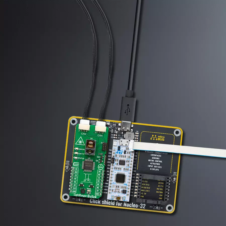
Click Shield for Nucleo-32 is the perfect way to expand your development board's functionalities with STM32 Nucleo-32 pinout. The Click Shield for Nucleo-32 provides two mikroBUS™ sockets to add any functionality from our ever-growing range of Click boards™. We are fully stocked with everything, from sensors and WiFi transceivers to motor control and audio amplifiers. The Click Shield for Nucleo-32 is compatible with the STM32 Nucleo-32 board, providing an affordable and flexible way for users to try out new ideas and quickly create prototypes with any STM32 microcontrollers, choosing from the various combinations of performance, power consumption, and features. The STM32 Nucleo-32 boards do not require any separate probe as they integrate the ST-LINK/V2-1 debugger/programmer and come with the STM32 comprehensive software HAL library and various packaged software examples. This development platform provides users with an effortless and common way to combine the STM32 Nucleo-32 footprint compatible board with their favorite Click boards™ in their upcoming projects.

Used MCU Pins
mikroBUS™ mapper
Take a closer look
Click board™ Schematic

Step by step
Project assembly

Start by selecting your development board and Click board™. Begin with the Nucleo 32 with STM32F031K6 MCU as your development board.


Track your results in real time
Application Output
1. Application Output - In Debug mode, the 'Application Output' window enables real-time data monitoring, offering direct insight into execution results. Ensure proper data display by configuring the environment correctly using the provided tutorial.

2. UART Terminal - Use the UART Terminal to monitor data transmission via a USB to UART converter, allowing direct communication between the Click board™ and your development system. Configure the baud rate and other serial settings according to your project's requirements to ensure proper functionality. For step-by-step setup instructions, refer to the provided tutorial.

3. Plot Output - The Plot feature offers a powerful way to visualize real-time sensor data, enabling trend analysis, debugging, and comparison of multiple data points. To set it up correctly, follow the provided tutorial, which includes a step-by-step example of using the Plot feature to display Click board™ readings. To use the Plot feature in your code, use the function: plot(*insert_graph_name*, variable_name);. This is a general format, and it is up to the user to replace 'insert_graph_name' with the actual graph name and 'variable_name' with the parameter to be displayed.

Software Support
Library Description
This library contains API for LightRanger 7 Click driver.
Key functions:
lightranger7_reset_device- This function resets the device by toggling the rst pin state.lightranger7_generic_write- This function writes a desired number of data bytes by using UART serial interface.lightranger7_generic_read- This function reads a desired number of data bytes by using UART serial interface.
Open Source
Code example
The complete application code and a ready-to-use project are available through the NECTO Studio Package Manager for direct installation in the NECTO Studio. The application code can also be found on the MIKROE GitHub account.
/*!
 * @file main.c
 * @brief LightRanger 7 Click Example.
 *
 * # Description
 * This example demonstrates the use of LightRanger 7 Click board by processing
 * the incoming data and displaying them on the USB UART.
 *
 * The demo application is composed of two sections :
 *
 * ## Application Init
 * Initializes the driver and performs the Click default configuration.
 *
 * ## Application Task
 * Reads and processes all incoming data and displays them on the USB UART.
 *
 * @note
 * By default, the Click board is programmed with the AFBR_S50_Example_RA4M2 firmware.
 * At the beginning this FW returns API version, chip ID, and module version. After that
 * it starts the measurements and prints the recent measurement results that consists of:
 *  1. Time stamp in seconds since the last MCU reset.
 *  2. Range in mm (converting the Q9.22 value to mm).
 *  3. Amplitude in LSB (converting the UQ12.4 value to LSB).
 *  4. Signal Quality in % (100% = good signal).
 *  5. Status (0: OK; < 0: Error; > 0: Warning.
 * For more information refer to the AFBR-S50 GitHub repository:
 * https://github.com/Broadcom/AFBR-S50-API
 *
 * ## Additional Function
 * - static void lightranger7_clear_app_buf ( void )
 * - static err_t lightranger7_process ( lightranger7_t *ctx )
 *
 * @author Stefan Filipovic
 *
 */

#include "board.h"
#include "log.h"
#include "lightranger7.h"

#define PROCESS_BUFFER_SIZE 200

static lightranger7_t lightranger7;
static log_t logger;

static uint8_t app_buf[ PROCESS_BUFFER_SIZE ] = { 0 };
static int32_t app_buf_len = 0;

/**
 * @brief LightRanger 7 clearing application buffer.
 * @details This function clears memory of application buffer and reset its length.
 * @note None.
 */
static void lightranger7_clear_app_buf ( void );

/**
 * @brief LightRanger 7 data reading function.
 * @details This function reads data from device and concatenates data to application buffer.
 * @param[in] ctx : Click context object.
 * See #lightranger7_t object definition for detailed explanation.
 * @return @li @c  0 - Read some data.
 *         @li @c -1 - Nothing is read.
 * See #err_t definition for detailed explanation.
 * @note None.
 */
static err_t lightranger7_process ( lightranger7_t *ctx );

void application_init ( void )
{
    log_cfg_t log_cfg;  /**< Logger config object. */
    lightranger7_cfg_t lightranger7_cfg;  /**< Click config object. */

    /**
     * Logger initialization.
     * Default baud rate: 115200
     * Default log level: LOG_LEVEL_DEBUG
     * @note If USB_UART_RX and USB_UART_TX
     * are defined as HAL_PIN_NC, you will
     * need to define them manually for log to work.
     * See @b LOG_MAP_USB_UART macro definition for detailed explanation.
     */
    LOG_MAP_USB_UART( log_cfg );
    log_init( &logger, &log_cfg );
    log_info( &logger, " Application Init " );

    // Click initialization.
    lightranger7_cfg_setup( &lightranger7_cfg );
    LIGHTRANGER7_MAP_MIKROBUS( lightranger7_cfg, MIKROBUS_1 );
    if ( UART_ERROR == lightranger7_init( &lightranger7, &lightranger7_cfg ) )
    {
        log_error( &logger, " Communication init." );
        for ( ; ; );
    }
    log_printf( &logger, " Reset device\r\n" );
    lightranger7_reset_device ( &lightranger7 );
    log_info( &logger, " Application Task " );
}

void application_task ( void )
{
    lightranger7_process( &lightranger7 );
    if ( app_buf_len > 0 )
    {
        log_printf( &logger, "%s", app_buf );
        lightranger7_clear_app_buf( );
    }
}

int main ( void )
{
    /* Do not remove this line or clock might not be set correctly. */
    #ifdef PREINIT_SUPPORTED
    preinit();
    #endif

    application_init( );

    for ( ; ; )
    {
        application_task( );
    }

    return 0;
}

static void lightranger7_clear_app_buf ( void )
{
    memset( app_buf, 0, app_buf_len );
    app_buf_len = 0;
}

static err_t lightranger7_process ( lightranger7_t *ctx )
{
    uint8_t rx_buf[ PROCESS_BUFFER_SIZE ] = { 0 };
    int32_t rx_size = 0;
    rx_size = lightranger7_generic_read( ctx, rx_buf, PROCESS_BUFFER_SIZE );
    if ( rx_size > 0 )
    {
        int32_t buf_cnt = app_buf_len;
        if ( ( ( app_buf_len + rx_size ) > PROCESS_BUFFER_SIZE ) && ( app_buf_len > 0 ) )
        {
            buf_cnt = PROCESS_BUFFER_SIZE - ( ( app_buf_len + rx_size ) - PROCESS_BUFFER_SIZE );
            memmove ( app_buf, &app_buf[ PROCESS_BUFFER_SIZE - buf_cnt ], buf_cnt );
        }
        for ( int32_t rx_cnt = 0; rx_cnt < rx_size; rx_cnt++ )
        {
            if ( rx_buf[ rx_cnt ] )
            {
                app_buf[ buf_cnt++ ] = rx_buf[ rx_cnt ];
                if ( app_buf_len < PROCESS_BUFFER_SIZE )
                {
                    app_buf_len++;
                }
            }
        }
        return LIGHTRANGER7_OK;
    }
    return LIGHTRANGER7_ERROR;
}

// ------------------------------------------------------------------------ END
Additional Support
Resources
Category:Optical


