Achieve precise speed and direction control for DC motors with TLE 6208-6 G and ATmega328P
Unleash the force within
Published Feb 14, 2024
Click board™
DC Motor 10 Click
Dev. board
Arduino UNO Rev3
Compiler
NECTO Studio
MCU
ATmega328P
Enhance your design, unlock the full potential of your DC motors, and attain versatile control across multiple operational modes
A
A
Hardware Overview
How does it work?
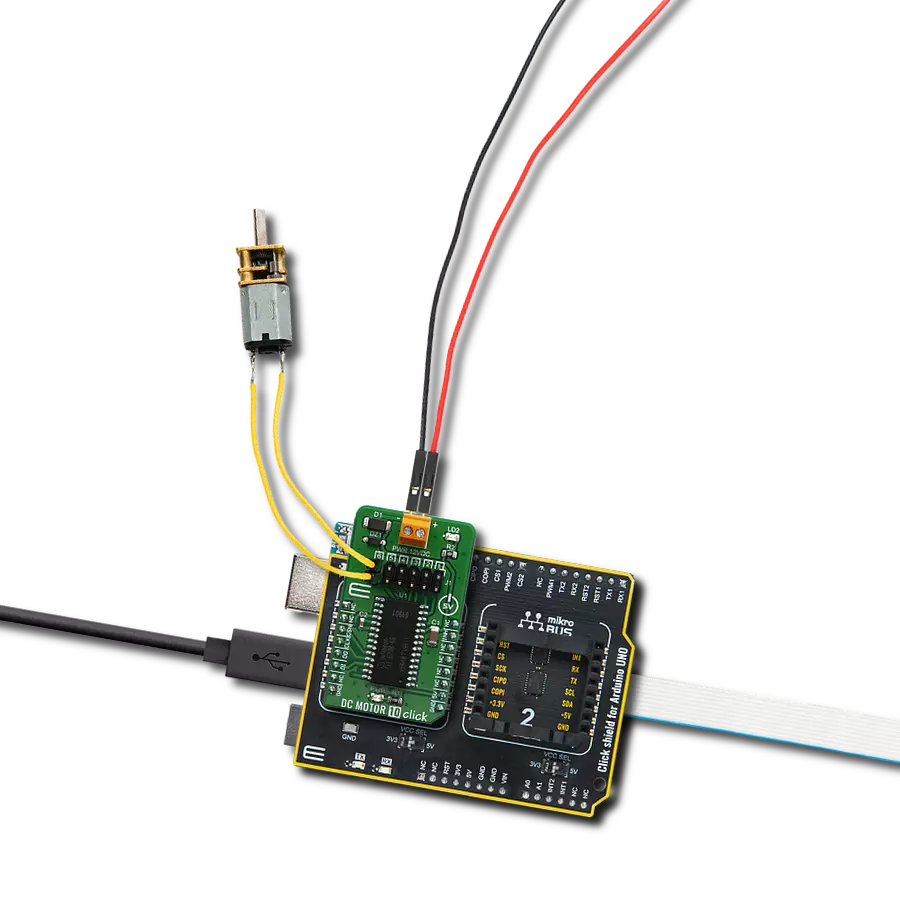
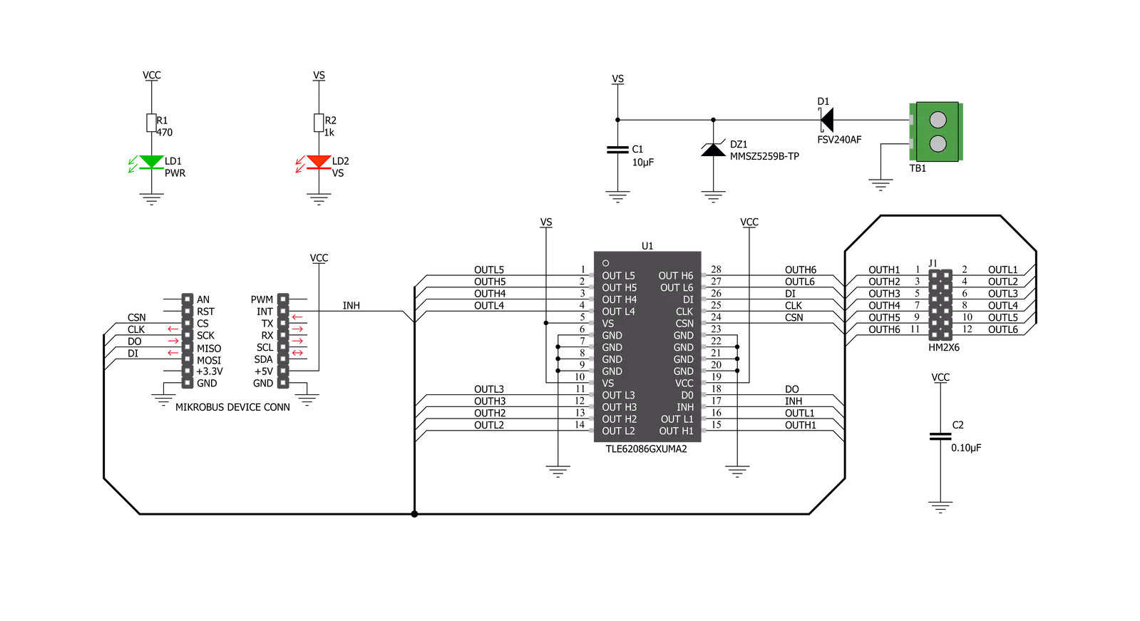
DC MOTOR 10 Click is based on the TLE 6208-6 G, a fully protected Hex-Half-Bridge-Driver explicitly designed for automotive and industrial motion control applications from Infineon Technologies. It integrates an efficient H-Bridge with a low ON resistance of approximately 0.8Ω through each branch. Furthermore, the built-in features like Over- and Undervoltage-Lockout, Over-Temperature-Protection, and the low quiescent current in standby mode open a wide range of automotive- and industrial applications. DC MOTOR 10 Click is ideally suited for the rapid development of various DC motor driving applications, including home appliances, printers, industrial equipment, mechatronic applications, and more. The part is based on Infineon Smart Power Technology SPT®, which
allows bipolar and CMOS control circuitry in accordance with DMOS power devices existing on the same monolithic circuitry. The six low and high-side drivers are freely configurable and can be controlled separately. Therefore all kinds of loads can be combined. In motion control, up to 5 actuators (DCMotors) can be connected to the six half-bridge outputs (cascade configuration). Operation modes forward (CW), reverse (CCW), brake, and high impedance are controlled from a standard SPI-Interface. Controlling the outputs via software from a central logic allows for limiting power dissipation. The internal logic of TLE 6208-6 G is supplied by the VCC voltage, typical with 5V. The VCC voltage uses an internally generated Power-On Reset (POR) to initialize
the module at Power-on. The advantage of this system is that information stored in the logic remains intact in the event of short-term failures in the supply voltage VS. The system can therefore continue to operate following VS undervoltage without having to be reprogrammed. The undervoltage information is stored and can be read out via the interface. This Click board™ can only be operated with a 5V logic voltage level. The board must perform appropriate logic voltage level conversion before using MCUs with different logic levels. However, the Click board™ comes equipped with a library containing functions and an example code that can be used as a reference for further development.

Features overview
Development board
Arduino UNO is a versatile microcontroller board built around the ATmega328P chip. It offers extensive connectivity options for various projects, featuring 14 digital input/output pins, six of which are PWM-capable, along with six analog inputs. Its core components include a 16MHz ceramic resonator, a USB connection, a power jack, an
ICSP header, and a reset button, providing everything necessary to power and program the board. The Uno is ready to go, whether connected to a computer via USB or powered by an AC-to-DC adapter or battery. As the first USB Arduino board, it serves as the benchmark for the Arduino platform, with "Uno" symbolizing its status as the
first in a series. This name choice, meaning "one" in Italian, commemorates the launch of Arduino Software (IDE) 1.0. Initially introduced alongside version 1.0 of the Arduino Software (IDE), the Uno has since become the foundational model for subsequent Arduino releases, embodying the platform's evolution.

Microcontroller Overview
MCU Card / MCU

Architecture
AVR
MCU Memory (KB)
32
Silicon Vendor
Microchip
Pin count
28
RAM (Bytes)
2048
You complete me!
Accessories
Click Shield for Arduino UNO has two proprietary mikroBUS™ sockets, allowing all the Click board™ devices to be interfaced with the Arduino UNO board without effort. The Arduino Uno, a microcontroller board based on the ATmega328P, provides an affordable and flexible way for users to try out new concepts and build prototypes with the ATmega328P microcontroller from various combinations of performance, power consumption, and features. The Arduino Uno has 14 digital input/output pins (of which six can be used as PWM outputs), six analog inputs, a 16 MHz ceramic resonator (CSTCE16M0V53-R0), a USB connection, a power jack, an ICSP header, and reset button. Most of the ATmega328P microcontroller pins are brought to the IO pins on the left and right edge of the board, which are then connected to two existing mikroBUS™ sockets. This Click Shield also has several switches that perform functions such as selecting the logic levels of analog signals on mikroBUS™ sockets and selecting logic voltage levels of the mikroBUS™ sockets themselves. Besides, the user is offered the possibility of using any Click board™ with the help of existing bidirectional level-shifting voltage translators, regardless of whether the Click board™ operates at a 3.3V or 5V logic voltage level. Once you connect the Arduino UNO board with our Click Shield for Arduino UNO, you can access hundreds of Click boards™, working with 3.3V or 5V logic voltage levels.

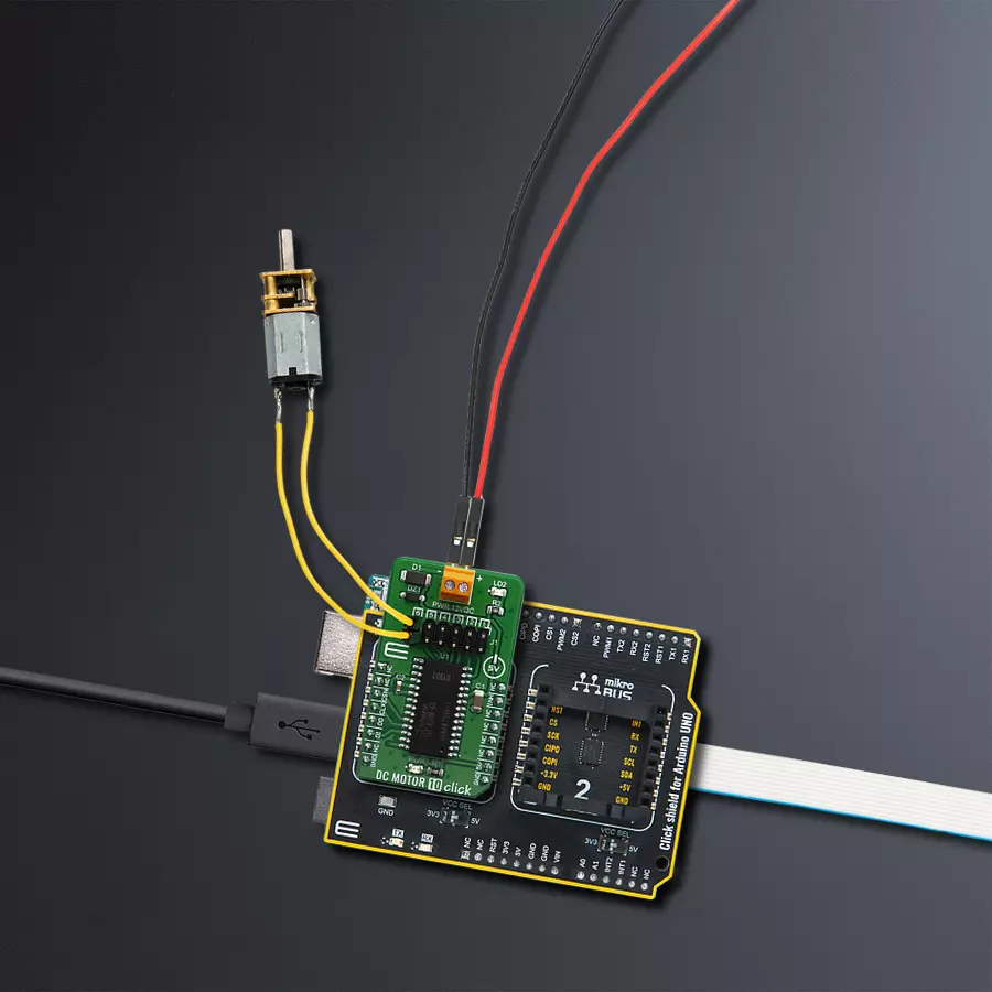
DC Gear Motor - 430RPM (3-6V) represents an all-in-one combination of a motor and gearbox, where the addition of gear leads to a reduction of motor speed while increasing the torque output. This gear motor has a spur gearbox, making it a highly reliable solution for applications with lower torque and speed requirements. The most critical parameters for gear motors are speed, torque, and efficiency, which are, in this case, 520RPM with no load and 430RPM at maximum efficiency, alongside a current of 60mA and a torque of 50g.cm. Rated for a 3-6V operational voltage range and clockwise/counterclockwise rotation direction, this motor represents an excellent solution for many functions initially performed by brushed DC motors in robotics, medical equipment, electric door locks, and much more.

Used MCU Pins
mikroBUS™ mapper
Take a closer look
Click board™ Schematic
Step by step
Project assembly

Start by selecting your development board and Click board™. Begin with the Arduino UNO Rev3 as your development board.


Track your results in real time
Application Output
1. Application Output - In Debug mode, the 'Application Output' window enables real-time data monitoring, offering direct insight into execution results. Ensure proper data display by configuring the environment correctly using the provided tutorial.

2. UART Terminal - Use the UART Terminal to monitor data transmission via a USB to UART converter, allowing direct communication between the Click board™ and your development system. Configure the baud rate and other serial settings according to your project's requirements to ensure proper functionality. For step-by-step setup instructions, refer to the provided tutorial.

3. Plot Output - The Plot feature offers a powerful way to visualize real-time sensor data, enabling trend analysis, debugging, and comparison of multiple data points. To set it up correctly, follow the provided tutorial, which includes a step-by-step example of using the Plot feature to display Click board™ readings. To use the Plot feature in your code, use the function: plot(*insert_graph_name*, variable_name);. This is a general format, and it is up to the user to replace 'insert_graph_name' with the actual graph name and 'variable_name' with the parameter to be displayed.

Software Support
Library Description
This library contains API for DC Motor 10 Click driver.
Key functions:
void dcmotor10_resetStatusReg();- Function is used to reset status register.void dcmotor10_enableChann1();- Function is used to enable channel 1.void dcmotor10_sendCommand( uint16_t wrData );- Function is used to send command.
Open Source
Code example
The complete application code and a ready-to-use project are available through the NECTO Studio Package Manager for direct installation in the NECTO Studio. The application code can also be found on the MIKROE GitHub account.
/*!
 * \file
 * \brief DcMotor10 Click example
 *
 * # Description
 * This example is running dc motors on channels 1 through 3.
 *
 * The demo application is composed of two sections :
 *
 * ## Application Init
 * Initalizes SPI, Click drivers and uninhibites the device.
 *
 * ## Application Task
 * This example demonstrates the use of DC MOTOR 10 Click by running dc motors
 * on channels 1 through 3, first all 3 together and then separately.
 *
 * \author Jovan Stajkovic
 *
 */
// ------------------------------------------------------------------- INCLUDES

#include "board.h"
#include "log.h"
#include "dcmotor10.h"

// ------------------------------------------------------------------ VARIABLES

static dcmotor10_t dcmotor10;
static log_t logger;

// ------------------------------------------------------ APPLICATION FUNCTIONS

void application_init ( void )
{
    log_cfg_t log_cfg;
    dcmotor10_cfg_t cfg;

    /**
     * Logger initialization.
     * Default baud rate: 115200
     * Default log level: LOG_LEVEL_DEBUG
     * @note If USB_UART_RX and USB_UART_TX
     * are defined as HAL_PIN_NC, you will
     * need to define them manually for log to work.
     * See @b LOG_MAP_USB_UART macro definition for detailed explanation.
     */
    LOG_MAP_USB_UART( log_cfg );
    log_init( &logger, &log_cfg );
    log_info( &logger, "---- Application Init ----" );

    //  Click initialization.

    dcmotor10_cfg_setup( &cfg );
    DCMOTOR10_MAP_MIKROBUS( cfg, MIKROBUS_1 );
    dcmotor10_init( &dcmotor10, &cfg );
    Delay_ms ( 100 );

    dcmotor10_inhibit(&dcmotor10, DCMOTOR10_UNINHIBIT );
    dcmotor10_send_cmd( &dcmotor10, DCMOTOR10_RESET_STATUS_REG );
    Delay_ms ( 100 );
}

void application_task ( void )
{
    dcmotor10_send_cmd( &dcmotor10, DCMOTOR10_ENABLE_1 | DCMOTOR10_ENABLE_2
                      | DCMOTOR10_ENABLE_3 );
    Delay_ms ( 1000 );
    Delay_ms ( 1000 );
    Delay_ms ( 1000 );
    Delay_ms ( 1000 );
    Delay_ms ( 1000 );
    dcmotor10_send_cmd( &dcmotor10, DCMOTOR10_ENABLE_1 );
    Delay_ms ( 1000 );
    Delay_ms ( 1000 );
    Delay_ms ( 1000 );
    Delay_ms ( 1000 );
    Delay_ms ( 1000 );
    dcmotor10_send_cmd( &dcmotor10, DCMOTOR10_ENABLE_2 );
    Delay_ms ( 1000 );
    Delay_ms ( 1000 );
    Delay_ms ( 1000 );
    Delay_ms ( 1000 );
    Delay_ms ( 1000 );
    dcmotor10_send_cmd( &dcmotor10, DCMOTOR10_ENABLE_3 );
    Delay_ms ( 1000 );
    Delay_ms ( 1000 );
    Delay_ms ( 1000 );
    Delay_ms ( 1000 );
    Delay_ms ( 1000 );
    dcmotor10_send_cmd( &dcmotor10, DCMOTOR10_RESET_STATUS_REG );
    Delay_ms ( 1000 );
}

int main ( void )
{
    /* Do not remove this line or clock might not be set correctly. */
    #ifdef PREINIT_SUPPORTED
    preinit();
    #endif

    application_init( );

    for ( ; ; )
    {
        application_task( );
    }

    return 0;
}

// ------------------------------------------------------------------------ END
Additional Support
Resources
Category:Brushed


