Experience a seamless blend of power and elegance with TB67H481FNG and ATmega328P
Powering tomorrow's movements

Published Feb 14, 2024
Click board™
DC Motor 13 Click
Dev. board
Arduino UNO Rev3
Compiler
NECTO Studio
MCU
ATmega328P
Enhance your engineering endeavors with our DC motor driver, a solution meticulously crafted to bring efficiency, precision, and innovation to your projects.
A
A
Hardware Overview
How does it work?
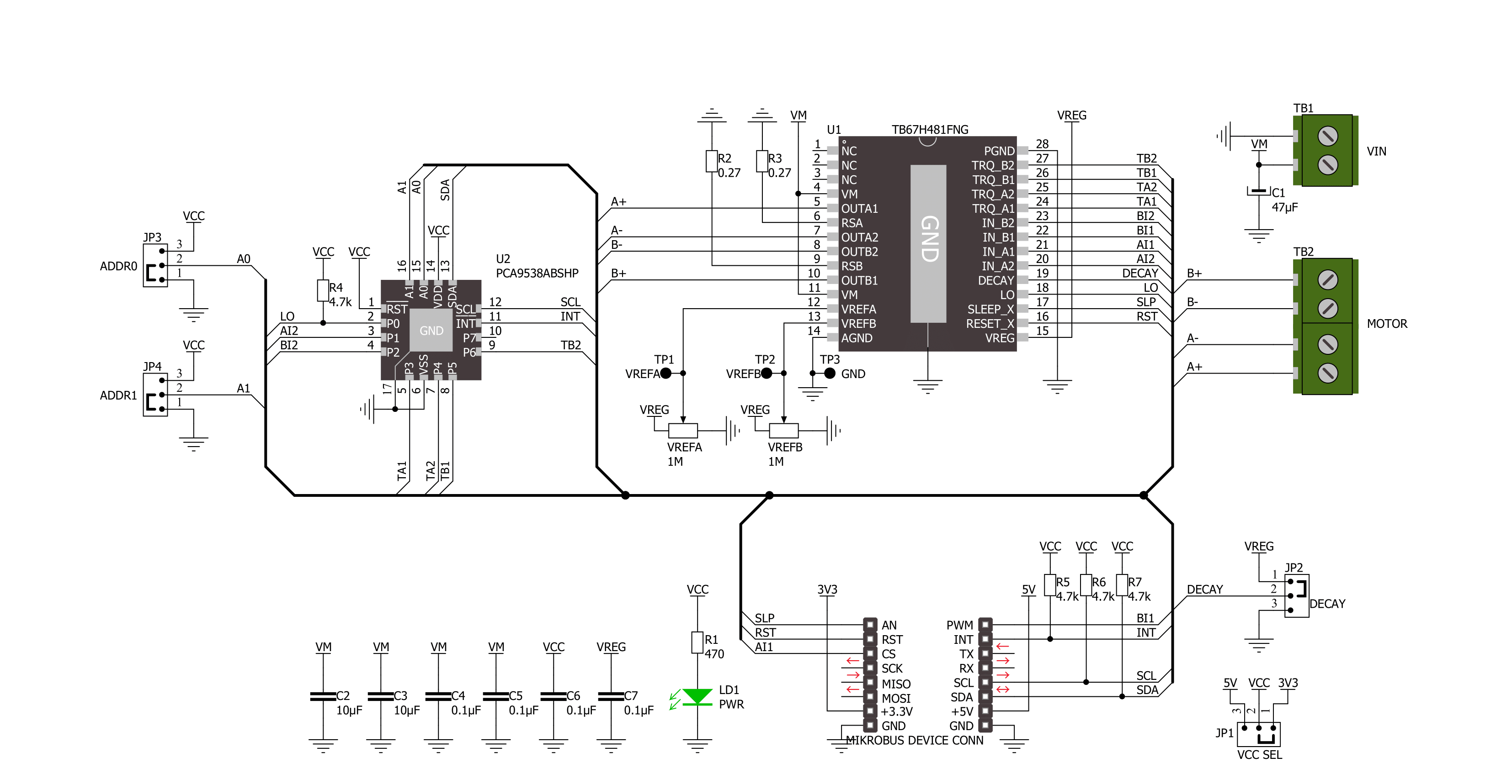
DC Motor 13 Click is based on the TB67H481FNG, a dual-channel, H-bridge, brushed DC motor driver from Toshiba Semiconductor. The TB67H481FNG has a current limit function that monitors the current flowing in the motor and performs constant current PWM control. When the motor current reaches the set current value, determined using onboard VREF trimmers (VREFA and VREFB), the TB67H481FNG shifts to Decay mode and annotates the current. Various Decay mode functions are selectable by positioning the SMD jumper, labeled as DECAY, to an appropriate position marked as 0 and 1. Also, Mixed Decay Mode can be selected by removing the JP2 jumper for the board. The TB67H481FNG has a built-in regulator that allows the motor to be driven by a single power supply, provides a motor output voltage rating of around 40V, and has integrated protection mechanisms such as over-current, over-temperature, and under-voltage
lockout for error detection. The setting current value can be adjusted with the torque function (100%, 71%, 38%, or 0%), controlled through the PCA9538A port expander, which establishes communication with the MCU via the I2C serial interface. Lowering the torque setting can suppress the motor current when high torque is unnecessary. In addition to these torque setting pins, with the help of the expander, it is also possible to control some other signals, such as the control signals for selecting the operating mode of the motor driver. These pins, in combination with AI1 and BI1 pins, routed to default positions of CS and PWM pins of the mikroBUS™ socket, enable operational modes like CW, CCW, or short-brake. The PCA9538A also allows choosing the least significant bit (LSB) of its I2C slave address by positioning SMD jumpers labeled as ADDR SEL to an appropriate position marked as 0 and 1, alongside its interrupt feature routed to the INT
pin of the mikroBUS™ socket. Besides, all circuits can be stopped using the Sleep function, routed to default positions of the AN pin of the mikroBUS™ socket, and thus enable power saving mode, while the RST pin provides a general-purpose reset function. The DC Motor 13 Click supports an external power supply for the TB67H481FNG, which can be connected to the input terminal labeled as VM and should be within the range of 8.2V to 44V, while the two brushed or one stepping motor coils can be connected to the terminals labeled as B+, B-, A-, and A+. This Click board™ can operate with either 3.3V or 5V logic voltage levels selected via the VCC SEL jumper. This way, both 3.3V and 5V capable MCUs can use the communication lines properly. Also, this Click board™ comes equipped with a library containing easy-to-use functions and an example code that can be used as a reference for further development.

Features overview
Development board
Arduino UNO is a versatile microcontroller board built around the ATmega328P chip. It offers extensive connectivity options for various projects, featuring 14 digital input/output pins, six of which are PWM-capable, along with six analog inputs. Its core components include a 16MHz ceramic resonator, a USB connection, a power jack, an
ICSP header, and a reset button, providing everything necessary to power and program the board. The Uno is ready to go, whether connected to a computer via USB or powered by an AC-to-DC adapter or battery. As the first USB Arduino board, it serves as the benchmark for the Arduino platform, with "Uno" symbolizing its status as the
first in a series. This name choice, meaning "one" in Italian, commemorates the launch of Arduino Software (IDE) 1.0. Initially introduced alongside version 1.0 of the Arduino Software (IDE), the Uno has since become the foundational model for subsequent Arduino releases, embodying the platform's evolution.

Microcontroller Overview
MCU Card / MCU

Architecture
AVR
MCU Memory (KB)
32
Silicon Vendor
Microchip
Pin count
28
RAM (Bytes)
2048
You complete me!
Accessories
Click Shield for Arduino UNO has two proprietary mikroBUS™ sockets, allowing all the Click board™ devices to be interfaced with the Arduino UNO board without effort. The Arduino Uno, a microcontroller board based on the ATmega328P, provides an affordable and flexible way for users to try out new concepts and build prototypes with the ATmega328P microcontroller from various combinations of performance, power consumption, and features. The Arduino Uno has 14 digital input/output pins (of which six can be used as PWM outputs), six analog inputs, a 16 MHz ceramic resonator (CSTCE16M0V53-R0), a USB connection, a power jack, an ICSP header, and reset button. Most of the ATmega328P microcontroller pins are brought to the IO pins on the left and right edge of the board, which are then connected to two existing mikroBUS™ sockets. This Click Shield also has several switches that perform functions such as selecting the logic levels of analog signals on mikroBUS™ sockets and selecting logic voltage levels of the mikroBUS™ sockets themselves. Besides, the user is offered the possibility of using any Click board™ with the help of existing bidirectional level-shifting voltage translators, regardless of whether the Click board™ operates at a 3.3V or 5V logic voltage level. Once you connect the Arduino UNO board with our Click Shield for Arduino UNO, you can access hundreds of Click boards™, working with 3.3V or 5V logic voltage levels.

DC Gear Motor - 430RPM (3-6V) represents an all-in-one combination of a motor and gearbox, where the addition of gear leads to a reduction of motor speed while increasing the torque output. This gear motor has a spur gearbox, making it a highly reliable solution for applications with lower torque and speed requirements. The most critical parameters for gear motors are speed, torque, and efficiency, which are, in this case, 520RPM with no load and 430RPM at maximum efficiency, alongside a current of 60mA and a torque of 50g.cm. Rated for a 3-6V operational voltage range and clockwise/counterclockwise rotation direction, this motor represents an excellent solution for many functions initially performed by brushed DC motors in robotics, medical equipment, electric door locks, and much more.

Used MCU Pins
mikroBUS™ mapper
Take a closer look
Click board™ Schematic
Step by step
Project assembly

Start by selecting your development board and Click board™. Begin with the Arduino UNO Rev3 as your development board.


Track your results in real time
Application Output
1. Application Output - In Debug mode, the 'Application Output' window enables real-time data monitoring, offering direct insight into execution results. Ensure proper data display by configuring the environment correctly using the provided tutorial.

2. UART Terminal - Use the UART Terminal to monitor data transmission via a USB to UART converter, allowing direct communication between the Click board™ and your development system. Configure the baud rate and other serial settings according to your project's requirements to ensure proper functionality. For step-by-step setup instructions, refer to the provided tutorial.

3. Plot Output - The Plot feature offers a powerful way to visualize real-time sensor data, enabling trend analysis, debugging, and comparison of multiple data points. To set it up correctly, follow the provided tutorial, which includes a step-by-step example of using the Plot feature to display Click board™ readings. To use the Plot feature in your code, use the function: plot(*insert_graph_name*, variable_name);. This is a general format, and it is up to the user to replace 'insert_graph_name' with the actual graph name and 'variable_name' with the parameter to be displayed.

Software Support
Library Description
This library contains API for DC Motor 13 Click driver.
Key functions:
dcmotor13_set_outa_mode- This function sets the OUTA mode.dcmotor13_set_outb_mode- This function sets the OUTB mode.dcmotor13_set_outa_torque- This function sets the OUTA torque.
Open Source
Code example
The complete application code and a ready-to-use project are available through the NECTO Studio Package Manager for direct installation in the NECTO Studio. The application code can also be found on the MIKROE GitHub account.
/*!
 * @file main.c
 * @brief DCMotor13 Click example
 *
 * # Description
 * This example demonstrates the use of DC Motor 13 Click board by driving the motors
 * in both direction in the span of 9 seconds.
 *
 * The demo application is composed of two sections :
 *
 * ## Application Init
 * Initializes the driver and performs the Click default configuration which sets the output
 * torque to 100%.
 *
 * ## Application Task
 * Drives the motors in the clockwise direction, then switches to the counter-clockwise direction,
 * and after that pulls the motors brake with a 3 seconds delay after each change.
 * Each step will be logged on the USB UART where you can track the program flow.
 *
 * @author Stefan Filipovic
 *
 */

#include "board.h"
#include "log.h"
#include "dcmotor13.h"

static dcmotor13_t dcmotor13;
static log_t logger;

void application_init ( void )
{
    log_cfg_t log_cfg;  /**< Logger config object. */
    dcmotor13_cfg_t dcmotor13_cfg;  /**< Click config object. */

    /**
     * Logger initialization.
     * Default baud rate: 115200
     * Default log level: LOG_LEVEL_DEBUG
     * @note If USB_UART_RX and USB_UART_TX
     * are defined as HAL_PIN_NC, you will
     * need to define them manually for log to work.
     * See @b LOG_MAP_USB_UART macro definition for detailed explanation.
     */
    LOG_MAP_USB_UART( log_cfg );
    log_init( &logger, &log_cfg );
    log_info( &logger, " Application Init " );

    // Click initialization.
    dcmotor13_cfg_setup( &dcmotor13_cfg );
    DCMOTOR13_MAP_MIKROBUS( dcmotor13_cfg, MIKROBUS_1 );
    if ( I2C_MASTER_ERROR == dcmotor13_init( &dcmotor13, &dcmotor13_cfg ) )
    {
        log_error( &logger, " Communication init." );
        for ( ; ; );
    }

    if ( DCMOTOR13_ERROR == dcmotor13_default_cfg ( &dcmotor13 ) )
    {
        log_error( &logger, " Default configuration." );
        for ( ; ; );
    }

    log_info( &logger, " Application Task " );
}

void application_task ( void )
{
    if ( DCMOTOR13_OK == dcmotor13_set_outa_mode ( &dcmotor13, DCMOTOR13_MODE_CW ) )
    {
        log_printf ( &logger, " OUTA: Clockwise\r\n" );
    }
    if ( DCMOTOR13_OK == dcmotor13_set_outb_mode ( &dcmotor13, DCMOTOR13_MODE_CW ) )
    {
        log_printf ( &logger, " OUTB: Clockwise\r\n\n" );
    }
    Delay_ms ( 1000 );
    Delay_ms ( 1000 );
    Delay_ms ( 1000 );
    if ( DCMOTOR13_OK == dcmotor13_set_outa_mode ( &dcmotor13, DCMOTOR13_MODE_CCW ) )
    {
        log_printf ( &logger, " OUTA: Counter-Clockwise\r\n" );
    }
    if ( DCMOTOR13_OK == dcmotor13_set_outb_mode ( &dcmotor13, DCMOTOR13_MODE_CCW ) )
    {
        log_printf ( &logger, " OUTB: Counter-Clockwise\r\n\n" );
    }
    Delay_ms ( 1000 );
    Delay_ms ( 1000 );
    Delay_ms ( 1000 );
    if ( DCMOTOR13_OK == dcmotor13_set_outa_mode ( &dcmotor13, DCMOTOR13_MODE_SHORT_BRAKE ) )
    {
        log_printf ( &logger, " OUTA: Short brake\r\n" );
    }
    if ( DCMOTOR13_OK == dcmotor13_set_outb_mode ( &dcmotor13, DCMOTOR13_MODE_SHORT_BRAKE ) )
    {
        log_printf ( &logger, " OUTB: Short brake\r\n\n" );
    }
    Delay_ms ( 1000 );
    Delay_ms ( 1000 );
    Delay_ms ( 1000 );
}

int main ( void )
{
    /* Do not remove this line or clock might not be set correctly. */
    #ifdef PREINIT_SUPPORTED
    preinit();
    #endif

    application_init( );

    for ( ; ; )
    {
        application_task( );
    }

    return 0;
}

// ------------------------------------------------------------------------ END
Additional Support
Resources
Category:Brushed


